Regulation control and energy management scheme for wireless power transfer

a technology of wireless power transfer and energy management, applied in the direction of battery/fuel cell control arrangement, electric devices, transportation and packaging, etc., to achieve the effect of optimal grid converter duty ratio d*, maximum power transfer rate at charging facilities, and maximum efficiency of power transfer

Active Publication Date: 2013-01-24
UT BATTELLE LLC
View PDF4 Cites 62 Cited by
  • Summary
  • Abstract
  • Description
  • Claims
  • Application Information

AI Technical Summary

Benefits of technology

[0005]Power transfer rate at a charging facility can be maximized by employing a feedback scheme. The state of charge (SOC) and temperature of the regenerative energy storage system (RESS) pack of a vehicle is monitored to determine the load due to the RESS pack. An optimal frequency that cancels the imaginary component of the input impedance for the output signal from a grid converter is calculated from the load of the RESS pack, and a frequency offset f* is made to the nominal frequency f0 of the grid converter output based on the resonance frequency of a magnetically coupled circuit. The optimal frequency can maximize the efficiency of the power transfer. Further, an optimal grid converter duty ratio d* can be derived from the charge rate of the RESS pack. The grid converter duty ratio d* regulates wireless power transfer (WPT) power level by adjusting the fundamental component of the primary voltage applied to the series resonant primary of the coupling coil assembly, thereby optimizing the power transfer rate to preserve the integrity of the RESS pack and / or to provide economical charging of the RESS pack.

Problems solved by technology

The most pressing issues facing wireless power transfer (WPT) charging of plug-in electric vehicles (PEV's) include interoperability, safety and emissions, and bidirectional communications.

Method used


Image

  • Regulation control and energy management scheme for wireless power transfer
  • Regulation control and energy management scheme for wireless power transfer
  • Regulation control and energy management scheme for wireless power transfer

Examples


Embodiment Construction

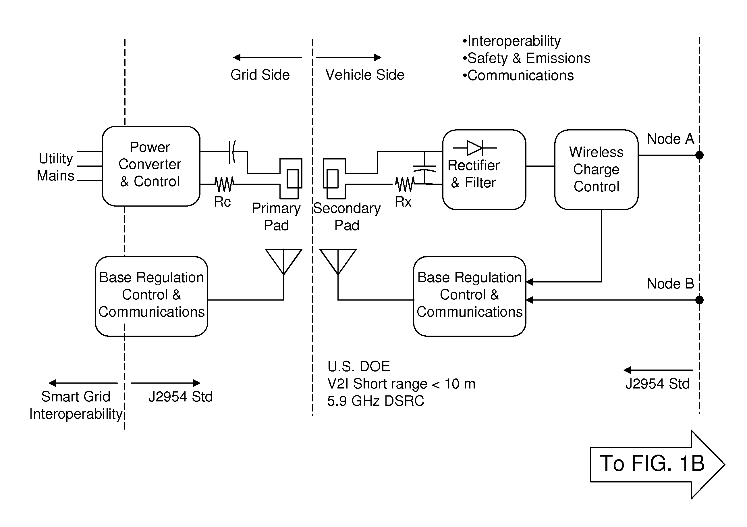
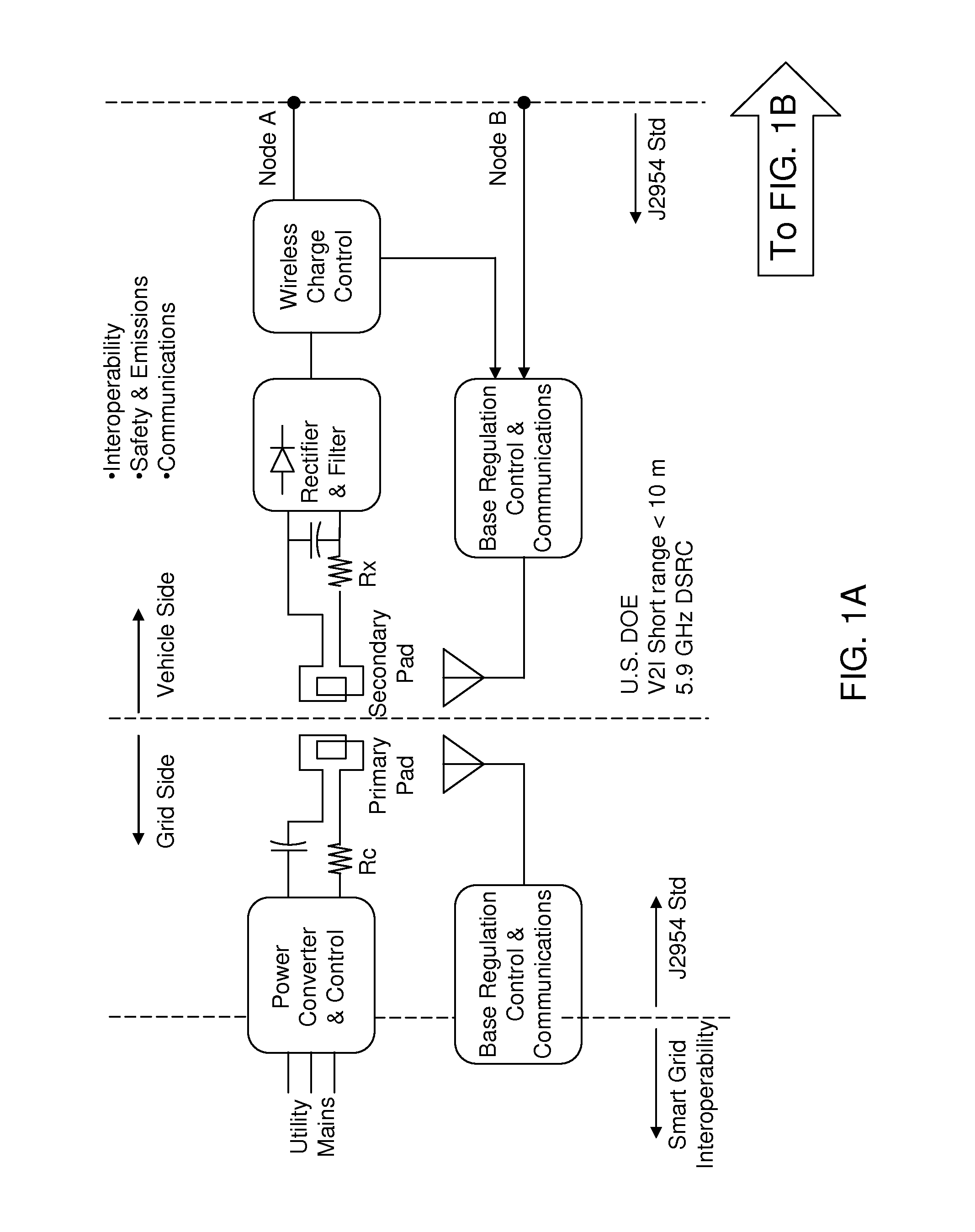
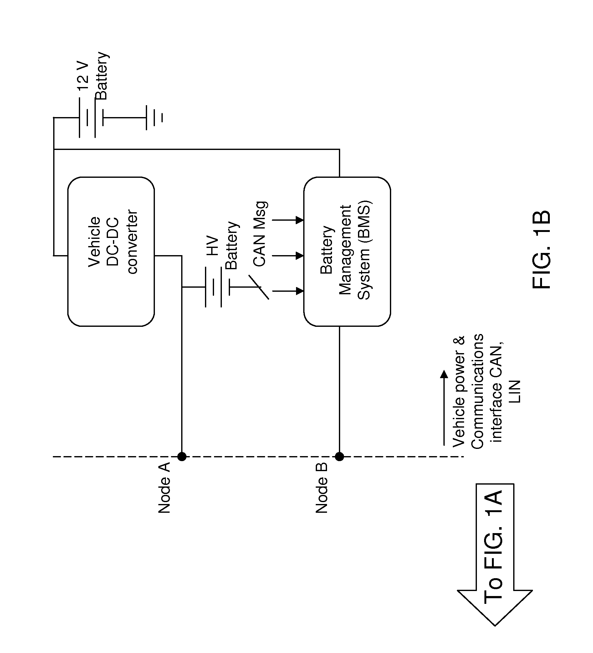
[0026]As stated above, the present invention relates to wireless power transfer for stationary charging and dynamic on-road charging of vehicles, which is now described in detail with accompanying figures. A vehicle may be an automobile, a shuttle, a trolley, a golf-type cart, a forklift, or any other type of electrified vehicle. The drawings are not drawn to scale.

[0027]As used herein, a “grid converter” herein refers to a device that takes alternating current (AC) supply voltage having a frequency less than 1 kHz and generated alternating current (AC) supply voltage having a frequency greater than 1 kHz.

[0028]To address the requirement of interoperability for wireless power transfer (WPT), global standardization of WPT operating frequency, coupling coil dimensions and locations on both parking space and vehicle, and the treatment of misalignment between the vehicle mounted receiver coil and the floor mounted (on or embedded in) transmit coil can be employed. For example, SAE J2954...


PUM


Abstract

Power transfer rate at a charging facility can be maximized by employing a feedback scheme. The state of charge (SOC) and temperature of the regenerative energy storage system (RESS) pack of a vehicle is monitored to determine the load due to the RESS pack. An optimal frequency that cancels the imaginary component of the input impedance for the output signal from a grid converter is calculated from the load of the RESS pack, and a frequency offset f* is made to the nominal frequency f0 of the grid converter output based on the resonance frequency of a magnetically coupled circuit. The optimal frequency can maximize the efficiency of the power transfer. Further, an optimal grid converter duty ratio d* can be derived from the charge rate of the RESS pack. The grid converter duty ratio d* regulates wireless power transfer (WPT) power level.

Description

CROSS-REFERENCE TO RELATED APPLICATIONS[0001]This application claims the benefit of priority from U.S. provisional application No. 61 / 510,210, filed on Jul. 21, 2011, the entire content of which is included here by reference.STATEMENT REGARDING FEDERALLY SPONSORED RESEARCH OR DEVELOPMENT[0002]This invention was made with United States government support under Prime Contract No. DE-AC05-00OR22725 awarded by the U.S. Department of Energy. The United States government has certain rights in this invention.FIELD OF THE INVENTION[0003]The present invention relates to the field of wireless power transfer for stationary charging and dynamic on-road charging of vehicles.BACKGROUND OF THE INVENTION[0004]Stationary charging refers to charging of a vehicle while the vehicle is stationary. Stationary charging can be performed, for example, at residential garages and public parking garage and ramps. Dynamic on-road charging refers to charging of a vehicle while the vehicle is on the road. The mos...

Claims


Application Information

Patent Timeline
Patent Type & Authority Applications(United States)
IPC IPC(8): H02J17/00B60L1/00
CPCH02J5/005H02J7/025Y02T90/122B60L11/182B60L11/1838B60L11/1861Y02T90/121Y02T10/7044Y02T10/7005Y02T10/705Y02T90/163Y02T90/14Y02T90/128B60L2240/545Y02T10/7072B60L58/12B60L53/126B60L53/122H02J2310/48H02J7/007182Y02T10/70H02J50/80H02J50/90H02J50/12H02J50/40H02J50/005Y02T90/12B60L53/12
Inventor MILLER, JOHN M.
Owner UT BATTELLE LLC
Why Eureka
Try Eureka