Encapsulated Stator

a stator and encapsulation technology, applied in the direction of supporting/enclose/casing, dynamo-electric components, control/drive circuits, etc., can solve the problems of poor operation efficiency adverse encapsulation effect, etc., to achieve waterproof effect and moisture-proof effect of the motor stator

Active Publication Date: 2013-01-24
SUNONWEALTH ELECTRIC MACHINE IND
View PDF25 Cites 17 Cited by
  • Summary
  • Abstract
  • Description
  • Claims
  • Application Information

AI Technical Summary

Benefits of technology

[0009]An objective of the present invention is to provide an encapsulated stator in which air gaps favorable to safe motor operation are provided between the encapsulated stator and a permanent magnet when the encapsulated stator is used in a motor.
[0010]Another objective of the present invention is to provide an encapsulated stator including a driving module with enhanced sealing structure.

Problems solved by technology

However, the air gaps between the permanent magnet and the pole plates 81 will be too small if the encapsulant 83 has a large thickness, leading to poor operational efficiency.
On the other hand, the encapsulating effect will be adversely affected if the thickness of the encapsulant 83 is too small, adversely affecting the waterproof effect and the moisture-proof effect of the motor stator 8.
Since the waterproof encapsulant 95 encapsulates both of the stator 92 and the separation sleeve 94, the air gaps between the permanent magnet and the stator 92 are decreased due to the thickness of the separation sleeve 94 and the waterproof encapsulant 95 when the motor stator 92 is coupled with a rotor to form a motor, resulting in safety risks during operation of the motor.

Method used


Image

  • Encapsulated Stator
  • Encapsulated Stator
  • Encapsulated Stator

Examples


Embodiment Construction

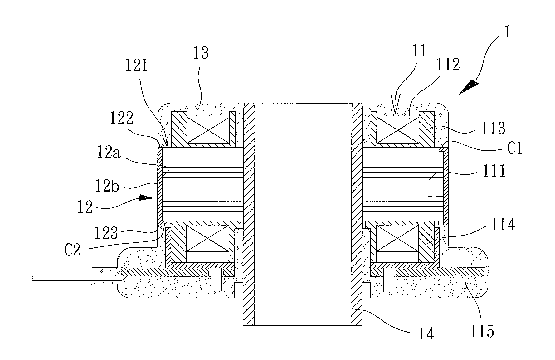
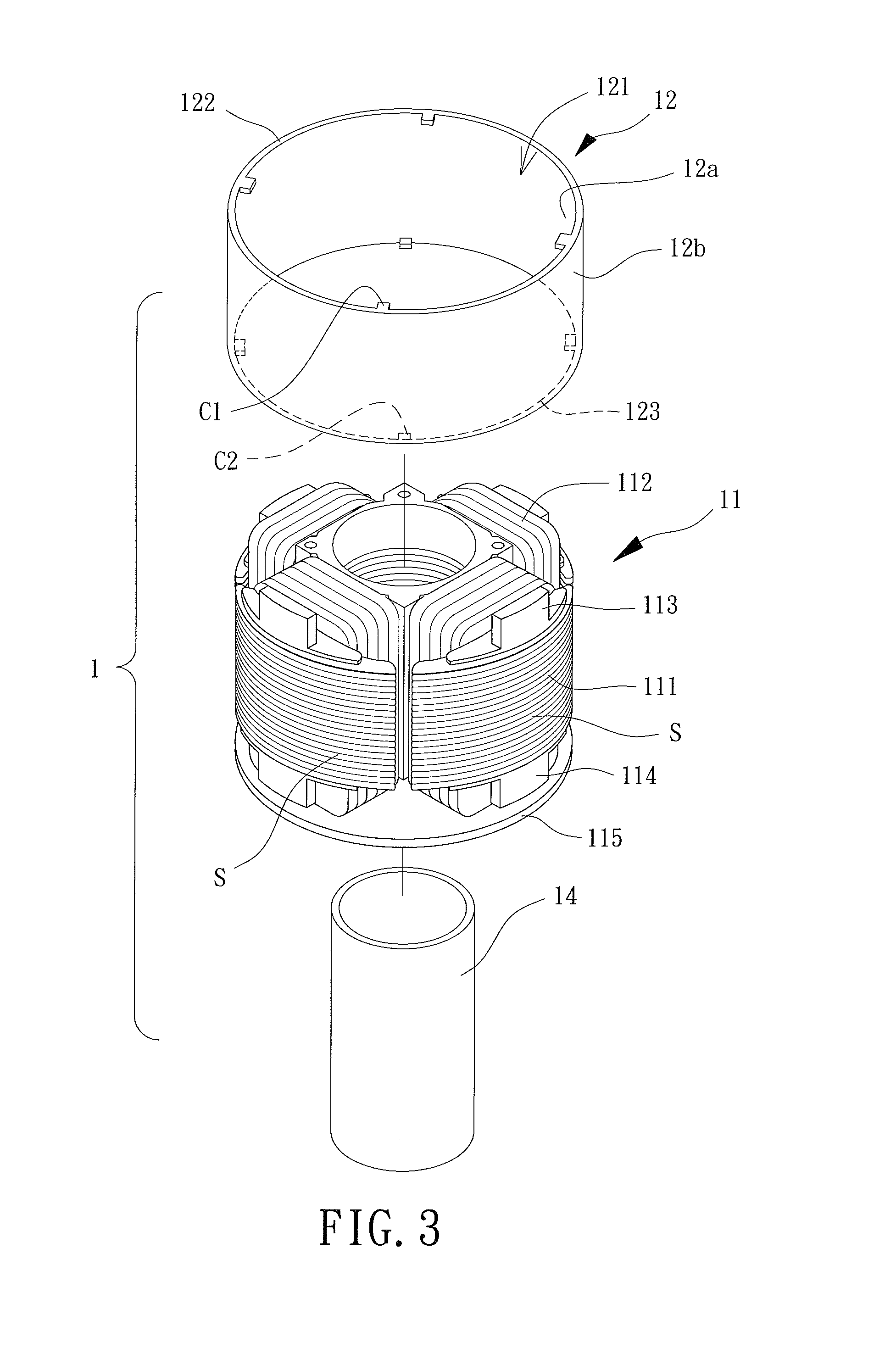
[0029]With reference to FIGS. 3 and 4, an encapsulated stator 1 of a first embodiment according to the present invention includes a driving module 11, a jacket 12 and an encapsulant 13. The jacket 12 is mounted to the driving module 11, and the encapsulant 13 encapsulates the driving module 11.

[0030]The driving module 11 is coupled to a shaft tube 14 that can be a metal shaft tube. The driving module 11 includes a silicon steel plate unit 111 and a coil unit 112. The silicon steel plate unit 111 is mounted to an outer periphery of the shaft tube 14. The coil unit 112 is wound around a predetermined portion of the silicon steel plate unit 111. Preferably, upper and lower insulating sleeves 113 and 114 are mounted to upper and lower ends of the silicon steel plate unit 111. The upper and lower insulating sleeves 113 and 114 are aligned with each other to allow easy winding of the coil unit 112 around outer peripheries of the upper and lower insulating sleeves 113 and 114. Thus, enhanc...


PUM


Abstract

An encapsulated stator includes a driving module coupled to a shaft tube. The driving module includes a silicon steel plate unit. A coil unit is wound around the silicon steel plate unit. A jacket is mounted to an outer periphery of the silicon steel plate unit of the driving module. The jacket includes an inner face and an outer face opposite to the inner face. The inner face of the jacket faces the driving module. An encapsulant is bonded to the driving module, the jacket, and the shaft tube. The encapsulant encapsulates the driving module. The encapsulant partially encapsulates the outer face of the jacket.

Description

BACKGROUND OF THE INVENTION[0001]1. Field of the Invention[0002]The present invention relates to an encapsulated stator and, more particularly, to a stator including a driving module encapsulated by an encapsulant.[0003]2. Description of the Related Art[0004]FIG. 1 shows a conventional motor stator 8 including a plurality of pole plates 81. Coils 82 are wound around the pole plates 81. The pole plates 81 and the coils 82 are encapsulated by a waterproof encapsulant 83 to provide a sealed structure. Thus, the motor stator 8 is waterproof and moisture-proof. An example of such a motor stator 8 is disclosed in Taiwan Patent No. 1266469 entitled “WATERPROOF STRUCTURE FOR BRUSHLESS MOTOR”.[0005]The motor stator 8 is coupled to a rotor to form a motor. Air gaps exist between a permanent magnet on the rotor and the pole plates 81. When the motor stator 8 is energized to create an alternating magnetic field that is induced by the permanent magnet, the magnetic lines of force created by the ...

Claims


Application Information

Patent Timeline
Patent Type & Authority Applications(United States)
IPC IPC(8): H02K1/04
CPCH02K5/128H02K5/08H02K11/0073H02K5/1675H02K1/187H02K11/33
Inventor HSIEH, KUN-LIWU, MING-FU
Owner SUNONWEALTH ELECTRIC MACHINE IND
Why Eureka
Try Eureka