Eureka AIR delivers breakthrough ideas for toughest innovation challenges, trusted by R&D personnel around the world.

Ink cartridge for inkjet printers

a technology for inkjet printers and ink cartridges, applied in printing and other directions, can solve problems such as unreliable sealing, and achieve the effect of reducing the resistance force against the installation of ink cartridges on the printhead and improving the seal structur

Inactive Publication Date: 2008-12-11
POWERFUL WAY
View PDF1 Cites 17 Cited by
  • Summary
  • Abstract
  • Description
  • Claims
  • Application Information

AI Technical Summary

Benefits of technology

[0003]An object of the present invention is to improve the structure of the seal for an ink outlet of an ink cartridge in order to ensure the reliability of sealing the ink outlet of the ink cartridge before and after the ink cartridge is installed to the printhead of an inkjet printer and to reduce the resistant force when the ink cartridge is installed to the printhead of an inkjet printer.
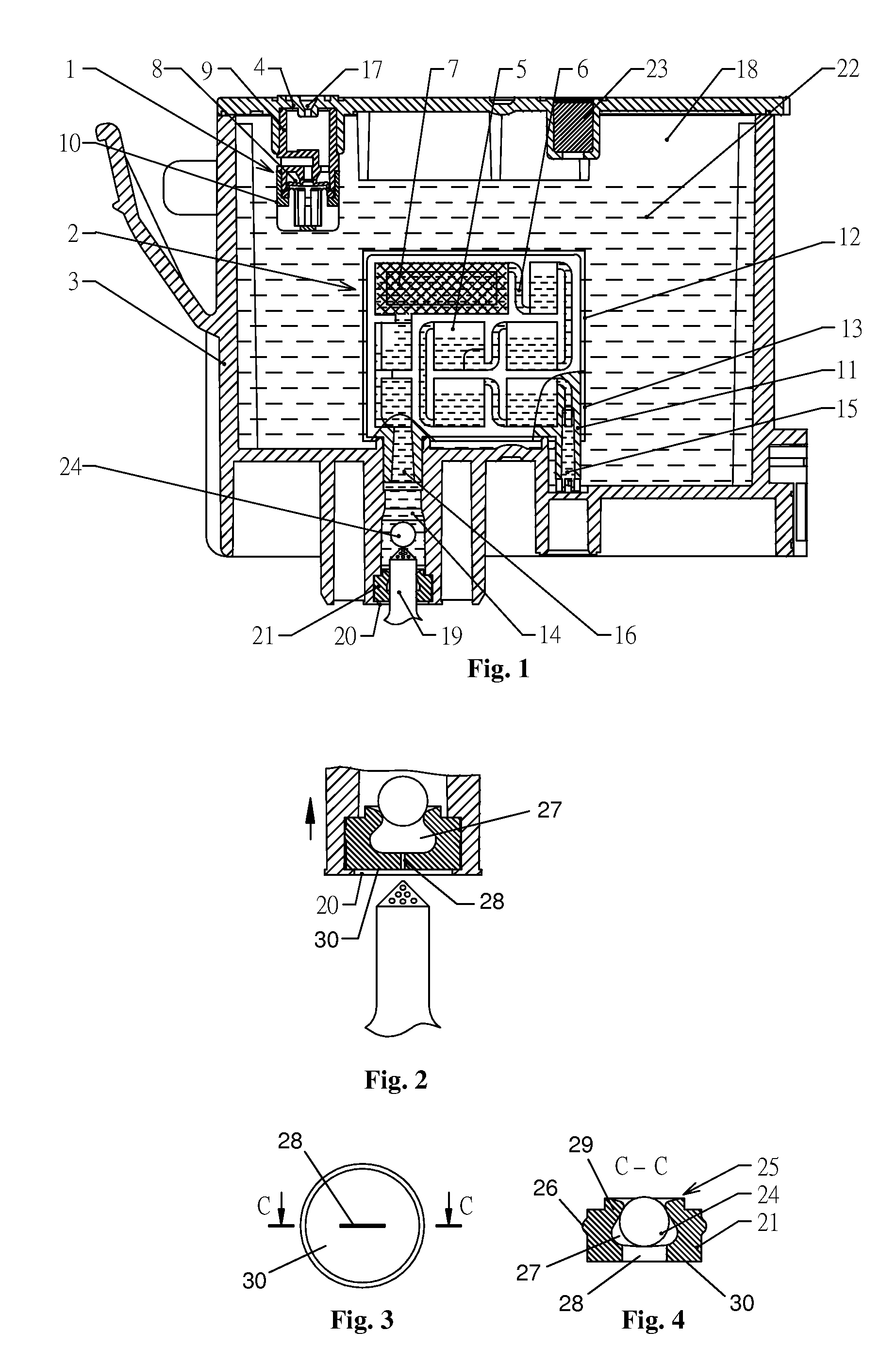
[0006]The inner chamber of the sealing member preferably has a small opening (i.e. one that is at least slightly smaller than the relevant outer dimension of the inner plug) with an inner side surface and an outer side surface that are both conical hole surfaces with large cone angles. The opening may expand by elastic deformation to allow the passage of the inner plug in both directions before shrinking back to its original structure, and is preferably bounded by a resilient skirt portion of the sealing member. Such an arrangement makes it easier to push the inner plug through the opening into the inner chamber to assemble the sealing plug, and also to push the inner plug out of the inner chamber through the opening when the ink cartridge is assembled to the printhead and the ink outlet needle comes into contact with the inner plug. It also allows the inner plug to be securely seated and come in contact with the outer side surface to close or seal the opening when the ink cartridge is no longer installed to the printhead.
[0007]The slit can be formed by a thin-edge cutting blade. The slit preferably cuts axially through the end face of the sealing member and is connected with the inner chamber and provides a fluid-tight seal with the ink outlet needle when the ink cartridge is installed to the printhead. The size of the slit is appropriately chosen such that it closes by itself into a self-sealing state when not being opened under the action of any external force. The slit therefore provides a fluid-tight seal to prevent the leakage of ink from the ink storage chamber at all times when the ink cartridge is not installed to the printhead (i.e. when the ink outlet needle of the printhead is not inserted through the slit).
[0012]The improved seal structure for the ink outlet of the ink cartridge can provide all kinds of sealing forms for the ink outlet of the ink cartridge before and after the installation of the ink cartridge to the printhead of an inkjet printer. Furthermore, since there is no plastic thin film welded on the outer end face of the ink outlet of the ink cartridge, the resistant force against the installation of the ink cartridge to the printhead is reduced and the sealing between the ink outlet of the ink cartridge and the ink outlet needle of the printhead becomes more reliable.

Problems solved by technology

Moreover, the irregular broken edges of the thin film can sometimes enter into the seal hole of the sealing member along with the ink outlet needle rendering the sealing unreliable.

Method used


Image

  • Ink cartridge for inkjet printers
  • Ink cartridge for inkjet printers

Examples


Embodiment Construction

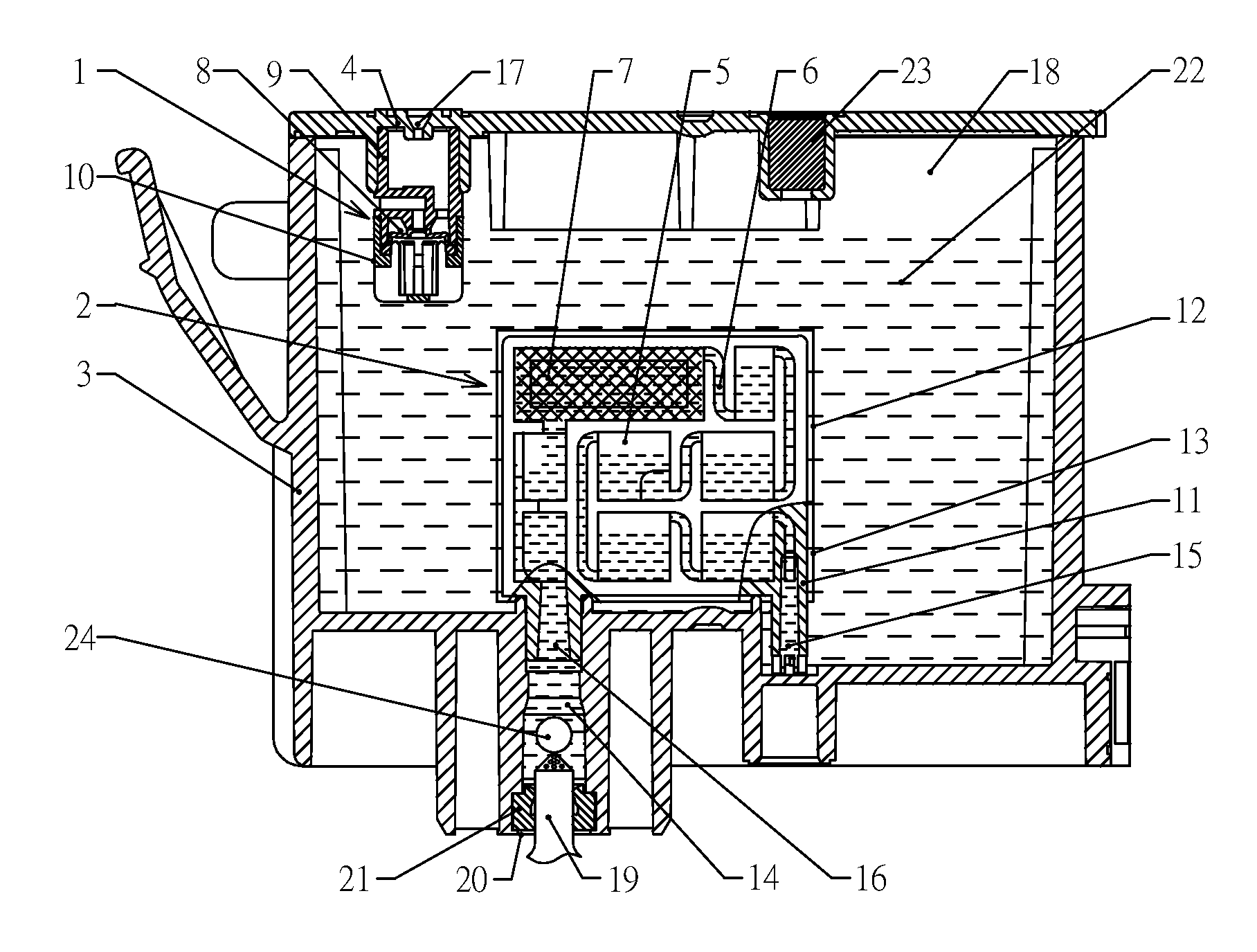
[0049]As shown in FIG. 1 to FIG. 4, an ink cartridge (sometimes called an ink box) includes five main components: an ink cartridge housing 3, an ink cartridge cover 4, an ink supply adjusting valve 2, an air inlet adjusting valve 1, and a sealing plug 25 for ink outlet of the ink cartridge.

[0050]The ink supply adjusting valve 2 which comprises a valve body 11, a filter mesh 7, a front film 12 and a rear film 13, may be assembled independently and is inserted into an upper end opening of an ink outlet 14 of the ink cartridge body 3 by an interference fit. The front and rear films 12 and 13 which are welded respectively to the front and rear surfaces of the valve body together with at least two through holes on the valve body 11 form the small ink chambers 5. The ink chambers 5 are connected by ink channels 6 which are long small grooves on the front and rear faces of the valve body 11 and act as damping orifice within the valve body 11. The ink chambers 5 are connected with each othe...


PUM


Abstract

An ink cartridge for an inkjet printer having a printhead with an ink outlet needle (19) comprises an ink cartridge body and a sealing plug (25). The ink cartridge body comprises an ink cartridge housing (3) and an ink cartridge cover (4) thereby forming an ink storage chamber (18). The sealing plug (25) is located in an ink outlet (14) of the ink cartridge body and has a sealing ring (26) formed on an outer substantially cylindrical surface thereof. The seal plug (25) comprises an elastic sealing member (21) having a slit (28) through which the ink outlet needle (19) of the printhead can be inserted and an inner chamber (27) respectively formed in two end faces thereof, and an inner plug (24) that is contained in the inner chamber (27).

Description

FIELD OF THE INVENTION[0001]The present invention relates to an ink cartridge for use in inkjet printers, and more particularly to an ink cartridge having an improved seal of the ink outlet.BACKGROUND OF THE INVENTION[0002]Chinese Patent Application 200620003627.3 describes an ink cartridge where an ink cartridge body is filled with ink but does not contain internal ink-absorbent materials (e.g. ink-storing foam). This means that the problem of having too much residual ink left in the ink-absorbent materials is avoided. Ink cartridges that lack ink-absorbent materials are also easier to recycle, cheaper to manufacture, and less polluting to the environment when discarded. The ink cartridge has an ink supply adjusting valve with a special structure, so that it can further solve the problems of the prior art in ink cartridges where the ink supply pressure adjusting structures being too complicated causing high manufacture costs and unguaranteed product quality. Also, inside the ink ca...

Claims


Application Information

Patent Timeline
Patent Type & Authority Applications(United States)
IPC IPC(8): B41J2/175
CPCB41J2/17513B41J2/17523B41J2/17553B41J2/17559B41J2/17596
Inventor NIP, SHUI KUEN
Owner POWERFUL WAY
Why Eureka
Eureka Blog
Learn More