Ball stud system for use within a ball joint

a technology of ball studs and studs, which is applied in the direction of threaded fasteners, screwdrivers, couplings, etc., can solve the problems of joint failure, nut slipping laterally along the flat face of the steering knuckle, and loss of torque in the nut that holds the stud in place, etc., to achieve less surface contact pressure, and better sealing structure

Active Publication Date: 2009-04-23
HONDA MOTOR CO LTD
View PDF16 Cites 17 Cited by
  • Summary
  • Abstract
  • Description
  • Claims
  • Application Information

AI Technical Summary

Benefits of technology

[0006]The ball stud system of the present invention provides a ball stud that will not fail or loosen easily under the application of repetitive side loading on the ball portion of the ball stud. The ball stud is secured to a vehicle's steering knuckle or other suspension component using the combination of a tapered nut and tapered washer. The tapered nut includes slots and the pin of the ball stud an aperture. A cotter pin may additionally be placed through the slots and aperture in order to further prevent rotation of the nut.
[0007]The present invention provides many benefits over the prior art. Because, under side loads, relative movement between the ball stud and suspension component is minimized, there is very little sinking of the ball stud into the suspension component. As a result the relative geometry of parts within the suspension, which is important to proper operation, is maintained.
[0009]The ball stud of the present invention can be secured to a suspension component that is made of a relatively soft material, such as aluminum, because less surface contact pressure is required between the ball stud and the suspension component. The clamping load is generated by a combination of normal force (force applied perpendicular to the stud or taper surface and creates surface contact pressure) and friction force. The friction force is a fraction of the normal force and acts in a direction along the taper surface. In a small taper joint, friction force carries most of the clamp load. Normal force balances the clamp load. The same clamp load generates far less surface contact pressure in large taper joints than in small taper joints.
[0010]The ball stud system of the present invention also provides a better sealing structure for the ball socket area as the seal used therein rests on a large tapered washer. The tapered washer is attached to the stud and seal prior to assembly with the suspension component (e.g. steering knuckle), whereas in a device not using such a washer, the seal connection is made with the vehicle component upon assembly. In addition, the washer surface is typically better machined than the vehicle component (e.g. steering knuckle) surface, thus, allowing the formation of a better seal.

Problems solved by technology

This sinking results in a loss of torque in the nut that holds the stud in place.
Once a certain amount of torque loss occurs, the joint is considered to have failed.
However, when a side load is applied at the center of the ball, the nut has a tendency to slip laterally along the flat face of the steering knuckle which it abuts.
Due to this slipping motion, the nut has a tendency to loosen, and thus fail the joint again, and does not provide a superior connection to the steering knuckle.

Method used


Image

  • Ball stud system for use within a ball joint
  • Ball stud system for use within a ball joint
  • Ball stud system for use within a ball joint

Examples


Embodiment Construction

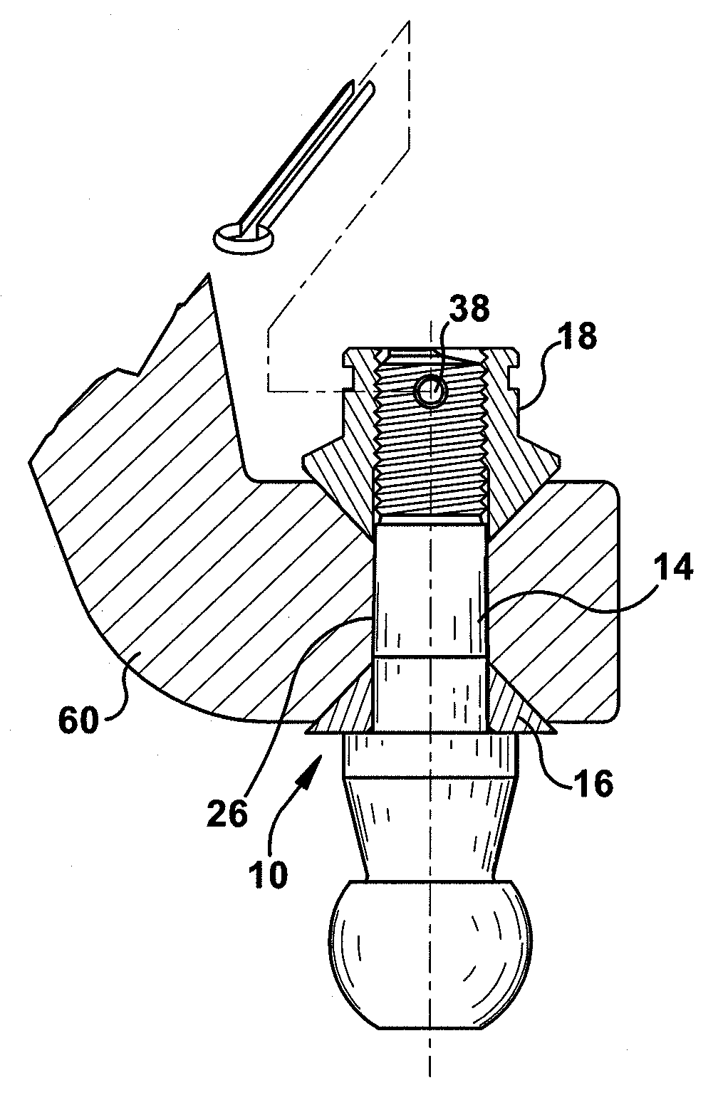
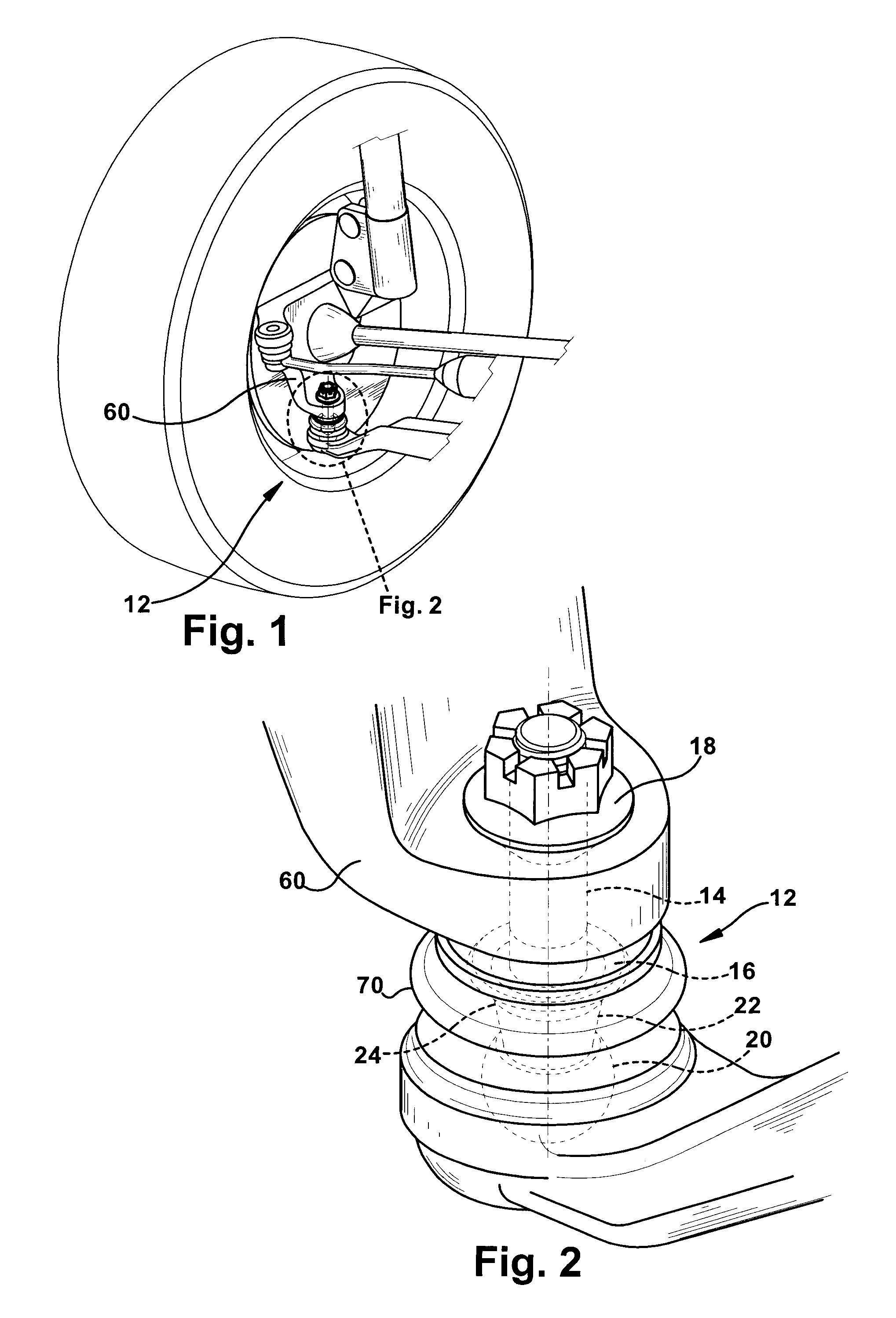
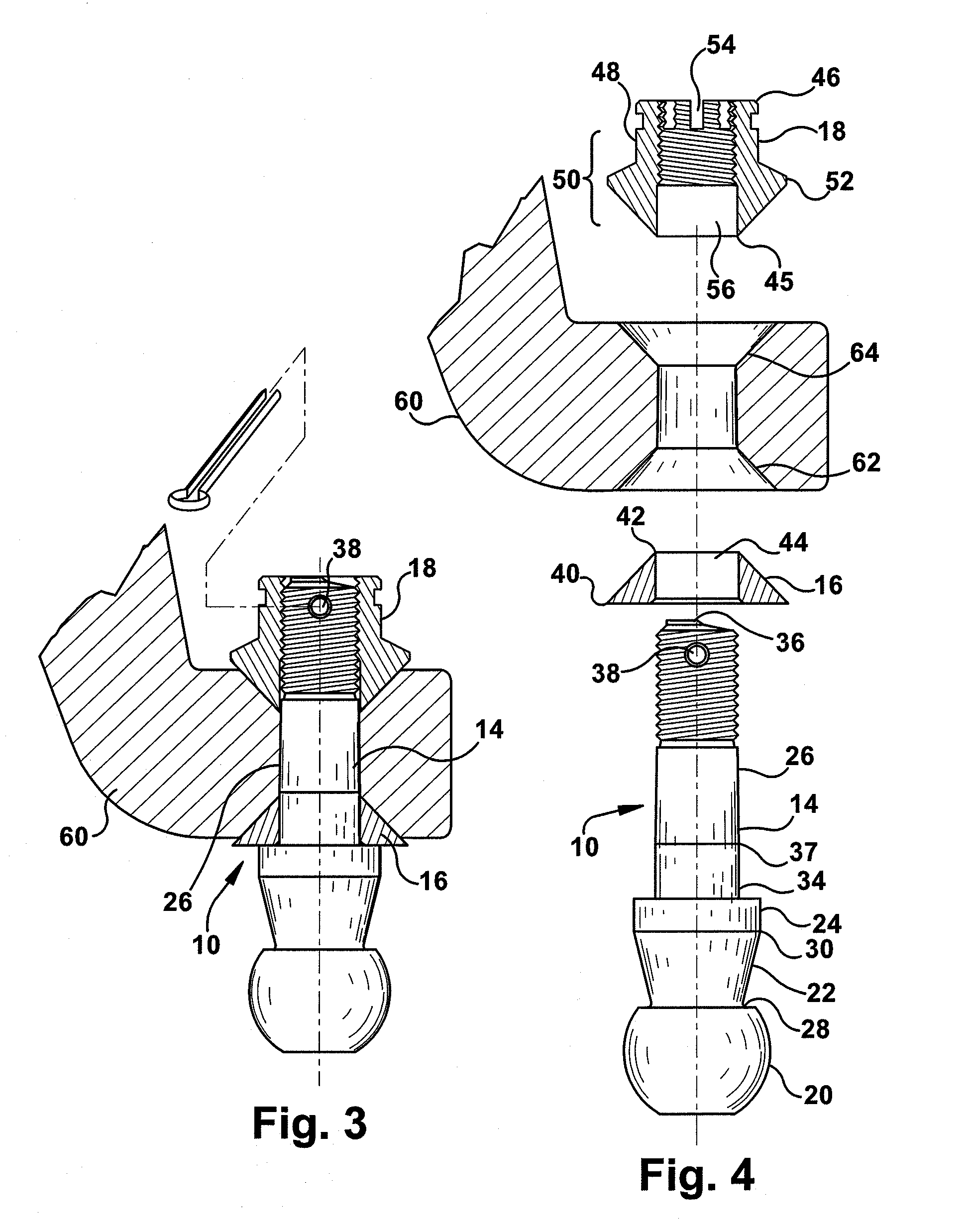
[0017]Schematically, and in a very simplified manner, FIGS. 1-4 show an exemplary embodiment of a ball stud system 10 according to the present invention for use within a vehicle ball joint 12. The ball stud 14 is not easily loosened during normal operation of the vehicle, i.e. torque within the nut securing the ball stud in place is not lost easily. The ball stud system 10 includes a ball stud 14, tapered washer 16 and tapered nut 18.

[0018]Referring to FIG. 4, the ball stud 14 is preferably formed from steel and includes, from the bottom up, a ball 20, a tapered neck 22, a shoulder 24, and a pin 26, all integrally formed. The preferred material of construction for the washer 16 and nut 18 is also steel. The ball 20 has a known generally spherical shape which merges at its top into an adjacent neck 22. At the bottom of the ball 20, the spherical shape, preferably, is truncated. The neck 22 is a truncated cone with a proximal end 28, adjacent the ball 20, having a smaller diameter tha...


PUM


Abstract

A ball stud system that provides a ball stud that will not loosen easily under the application of repetitive side loading on the ball portion of the stud. The ball stud is secured to the vehicle steering knuckle arm using the combination of a tapered nut and tapered washer. The tapered nut includes slots and the pin of the ball stud an aperture. A cotter pin may be placed through the slots and aperture in order to further prevent rotation of the nut.

Description

BACKGROUND OF THE INVENTION[0001]Ball joints have been used for years within automobiles, particularly within automobile suspensions. As an example, a typical ball joint operatively connects a control arm to a steering knuckle within the automobile's steering system. The ball joint includes a ball stud and a socket. The ball stud gets attached to the steering knuckle. A pin portion of the ball stud is usually tapered in some manner and fits into a matching tapered hole in the steering knuckle. A distal end of the pin is typically threaded and a nut is attached thereto in order to hold the pin within the steering knuckle. The socket gets attached to the control arm. The socket fits over a spherical ball portion of the ball stud and permits relative universal rotation between the steering knuckle and control arm. Ball joints are also used in other areas of vehicle suspensions.[0002]In existing practice, many types of ball stud designs are used, including a small taper pin design and a...

Claims


Application Information

Patent Timeline
Patent Type & Authority Applications(United States)
IPC IPC(8): F16C11/06
CPCB62D7/18F16B9/026Y10T403/32737Y10T403/32614F16B39/04
Inventor DENDIS, CHRISTOPHERCHEN, LIXINMORAVY, LARS DAVID
Owner HONDA MOTOR CO LTD
Why Eureka
Try Eureka