Electronic device with ring-connected hall effect regions

Active Publication Date: 2013-01-24
INFINEON TECH AG
View PDF1 Cites 69 Cited by
  • Summary
  • Abstract
  • Description
  • Claims
  • Application Information

AI Technical Summary

Benefits of technology

[0007]Further embodiments of the present invention provide an electronic device comprising: a first Hall effect region, a second Hall effect region, a third Hall effect region, and a fourth Hall effect region that are isolated from each other. Each Hall effect region comprises a first contact, a second contact, a supply contact, and a sense contact in or on surfaces of the Hall effect region. The first contact of the second Hall effect region is connected to the second contact of the first Hall effect region and the first contact of the first Hall effect region is connected to the second contact of the second Hall effect region, so that two current paths exist between the supply contact of the first Hall effect region and the supply contact of the second Hall effect region. The first contact of the fourth Hall effect region is connected to the second contact of the third Hall effect region and the first contact of the third Hall effect region is connected to the second contact of the fourth Hall effect region, so that two current paths exist between the supply contact of the third Hall effect region and the supply contact of the fourth Hall effect region. The supply contacts and the sense contacts are arranged in a sequence along each one of the current paths such that there is one sense contact of the sense contacts between two of the supply contacts. A first differential sense signal is tapped between the sense contacts of the first and third Hall effect regions and a second differential sense signal is tapped between the sense contacts of the second and fourth Hall effect regions.
[0008]Further embodiments of the present invention provide an electronic device, comprising: four Hall effect regions that are isolated from each other, wherein each of the four Hall effect regions comprises a first contact and a second contact in or on a surface of the Hall effect region. A first contact of the (k+1)-th Hall effect region is connected to a second contact of the k-th Hall effect region for k=1 to 3, and a first contact of the first Hall effect region is connected to a second contact of the fourth Hall effect region. Each of the four Hall effect regions further comprises one of a supply contact and a sense contact in or on the surface of the Hall effect region, the supply contact or the sense contact being arranged between the first contact and the second contact of the Hall effect region. A Hall effect region in or on the surface of which a supply contact is formed is connected via its first and second contacts to two Hall effect regions in or on the surfaces of which a sense contact is formed, respectively, so that the supply contacts and the sense contacts are arranged in a sequence along a current path between at least two supply contacts such that there is one sense contact between the at least two supply contacts. Each Hall effect region comprises at most one of the at least two supply contacts.
[0009]Further embodiments according to the teachings disclosed herein provide an electronic device comprising a first Hall effect region and a second Hall effect region, at least four spinning current contacts, and at least four ring-contacting contacts. The first and second Hall effec

Problems solved by technology

Most vertical Hall devices suffer from the fact that the spinning current method, which is used to cancel the zero-point error of the Hall devices, does not work v

Method used


Image

  • Electronic device with ring-connected hall effect regions
  • Electronic device with ring-connected hall effect regions
  • Electronic device with ring-connected hall effect regions

Examples


Embodiment Construction

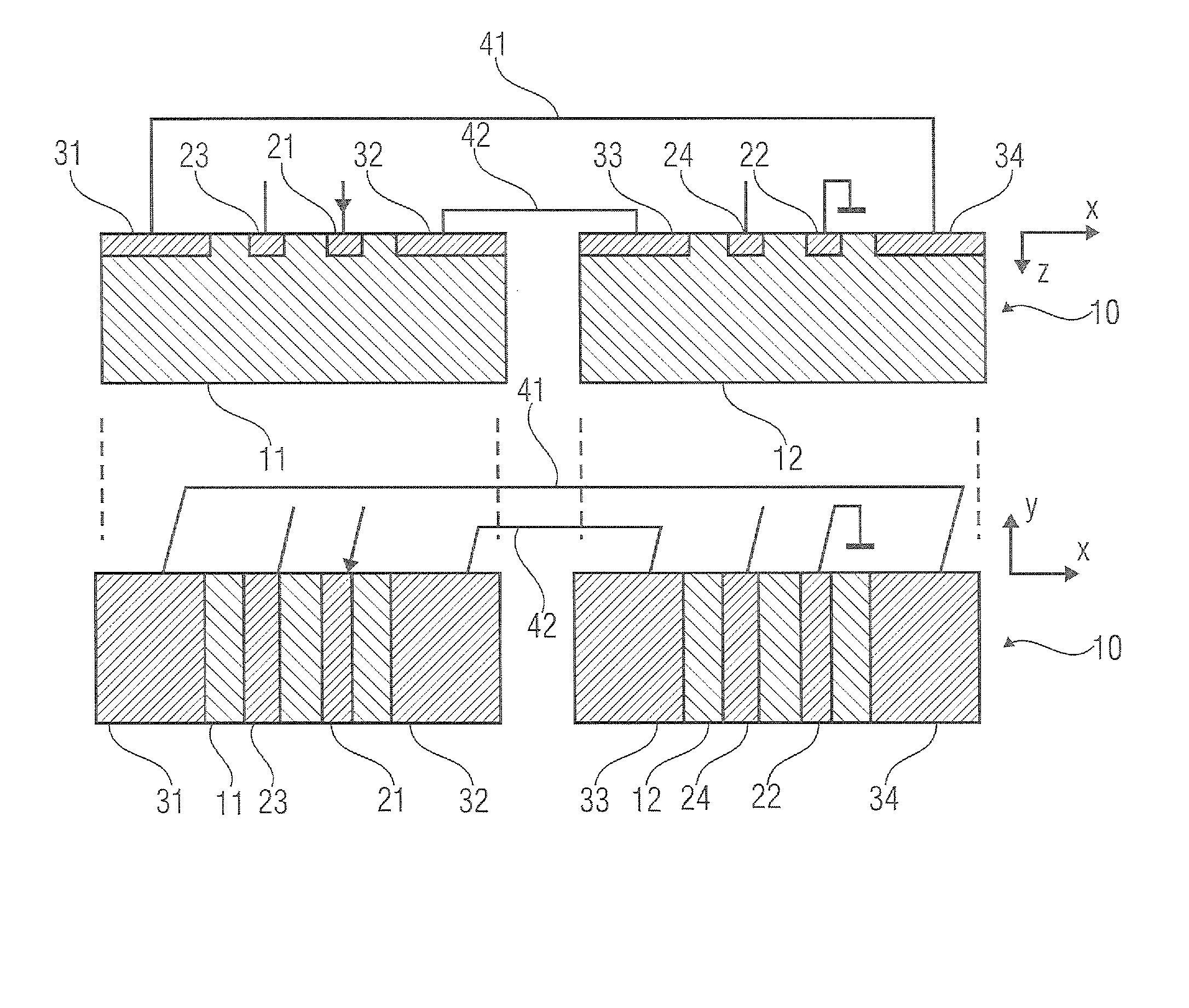
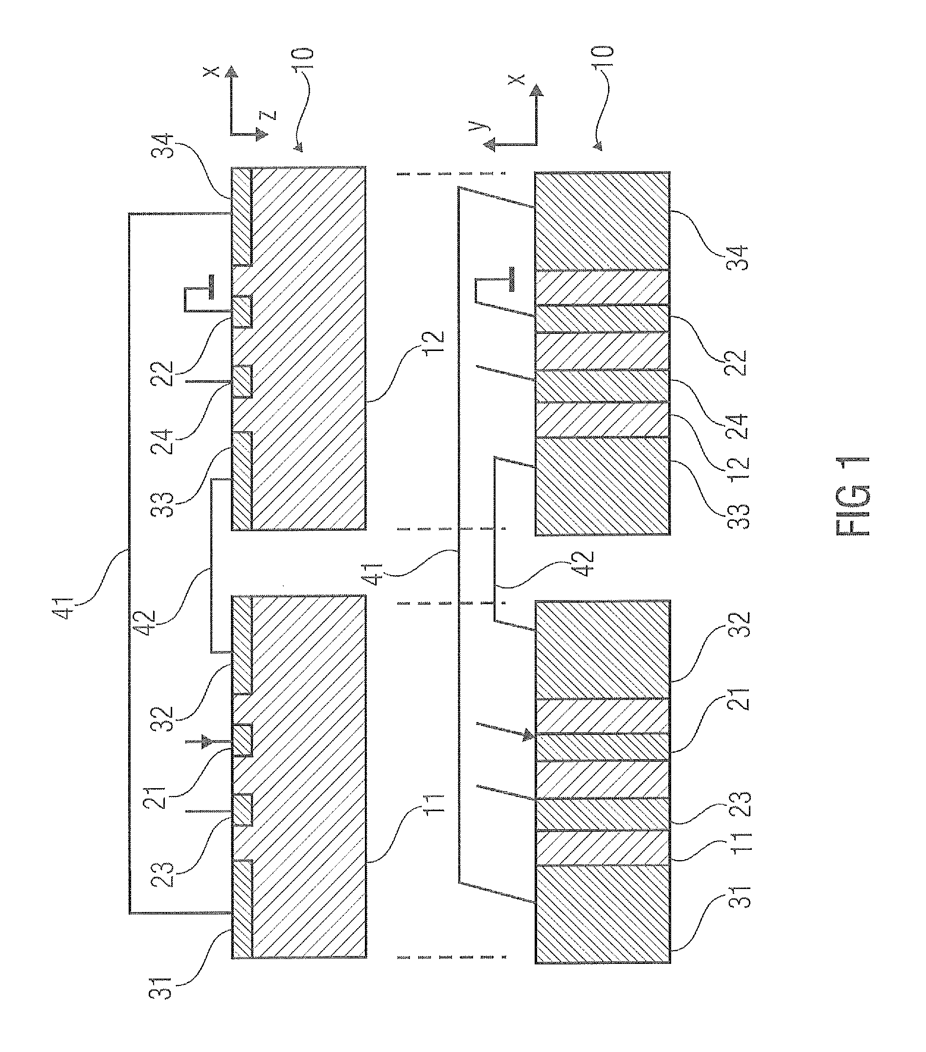
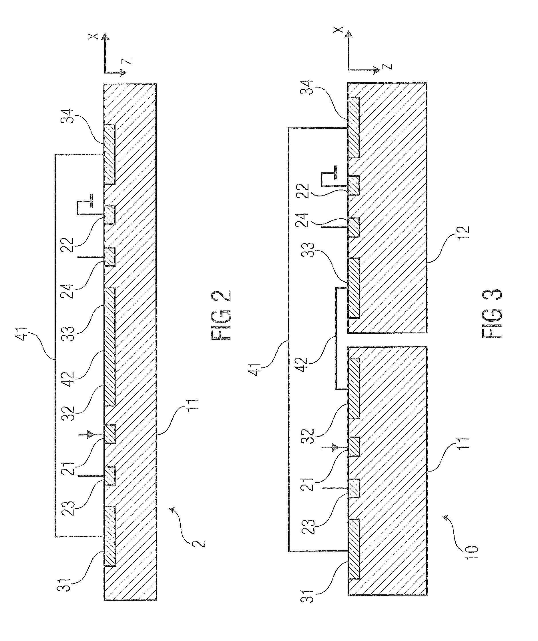
[0041]In the following description, a plurality of details are set forth to provide a more thorough explanation of embodiments of the teachings disclosed herein. However, it will be apparent to one skilled in the art that embodiments of the teachings disclosed herein may be practiced without these specific details. Features of the different embodiments described hereinafter may be combined with each other, unless specifically noted otherwise. For the most part, the terms “Hall effect region” and “tub” are used interchangeably herein. Accordingly, a Hall effect region may be a tub or well of a first conductivity type which is embedded in a substrate or a tub of opposite conductivity type. This structure may cause an electrical isolation of the tub against the substrate in particular if the resulting pn-junction is reverse biased. However, it may also be possible that one tub comprises two or more Hall effect regions, in particular when two or more relatively distinct current flows ca...


PUM


Abstract

An electronic device includes a number of n Hall effect regions with n>1, wherein the n Hall effect regions are isolated from each other. The electronic device also includes at least eight contacts in or on surfaces of the n Hall effect regions, wherein the contacts include: a first and a second contact of each Hall effect region. A first contact of the (k+1)-th Hall effect region is connected to the second contact of the k-th Hall effect region for k=1 to n−1, and the first contact of the first Hall effect region is connected to the second contact of the n-th Hall effect region. The at least eight contacts include at least two supply contacts and at least two sense contacts. Each Hall effect region includes at most one of the at least two supply contacts and at most one of the at least two sense contacts.

Description

RELATED APPLICATION[0001]This application is related to U.S. Ser. No. ______ filed on ______ entitled “VERTICAL HALL SENSOR WITH HIGH ELECTRICAL SYMMETRY” (Attorney Docket No. SZP189US).FIELD OF THE INVENTION[0002]Embodiments of the present invention relate to an electronic device and to a sensing method. In particular, the electronic device may be a sensing device for sensing a physical quantity such as a magnetic field or a mechanical stress within an object.BACKGROUND OF THE INVENTION[0003]Electronic devices may be used to sense or measure physical quantities. In order to sense or measure the strength and direction of a magnetic field parallel to the surface of, e.g., a semiconductor die, vertical Hall devices may be used. Most vertical Hall devices suffer from the fact that the spinning current method, which is used to cancel the zero-point error of the Hall devices, does not work very well. With known methods of the spinning current scheme it is possible to obtain residual zero...

Claims


Application Information

Patent Timeline
IPC IPC(8): G01R33/06
CPCG01R33/072G01L1/12G01R33/07G01D5/145H10N52/101H10N52/80
Inventor AUSSERLECHNER, UDO
Owner INFINEON TECH AG
Why Eureka
Try Eureka