Illumination apparatus and plant cultivation apparatus

a technology of plant cultivation and illumination apparatus, which is applied in the direction of light-emitting diodes, semiconductor devices of light sources, planar light sources, etc., can solve the problems of not containing infrared rays, occupying a lot of space, and conventional light sources are less advantageous in light use efficiency. , to achieve the effect of easy control of the light distribution of a light-emitting diod

Inactive Publication Date: 2013-01-24
SHARP KK
View PDF2 Cites 42 Cited by
  • Summary
  • Abstract
  • Description
  • Claims
  • Application Information

AI Technical Summary

Benefits of technology

[0024]According to an illumination apparatus and a plant cultivation apparatus of the present invention, it is possible to easily control light distribution of a light-emitting diode by changing optical members depending on the purposes. Further, since the optical ...

Problems solved by technology

In addition, the LEDs do not contain any infrared rays or heat rays, which are contained in a large amount in conventional light sources such as incandescent lamps, fluorescent lamps, metal halide lamps, and high-pressure sodium lamps.
That is, conventional light sources are less advantageous in light use efficiency, because, according to the conventional light sources, it is ne...

Method used


Image

  • Illumination apparatus and plant cultivation apparatus
  • Illumination apparatus and plant cultivation apparatus
  • Illumination apparatus and plant cultivation apparatus

Examples


embodiment 1

[0037]One embodiment of the present invention is described below with reference to FIG. 1 to FIG. 9. Note however that, unless otherwise specifically stated, the dimensions, materials, shapes, relative positions etc. of constituents described in the present embodiment do not imply any limitation on the scope of the present invention, and therefore are mere examples for descriptions.

[0038](Schematic Configuration of Plant Cultivation Apparatus)

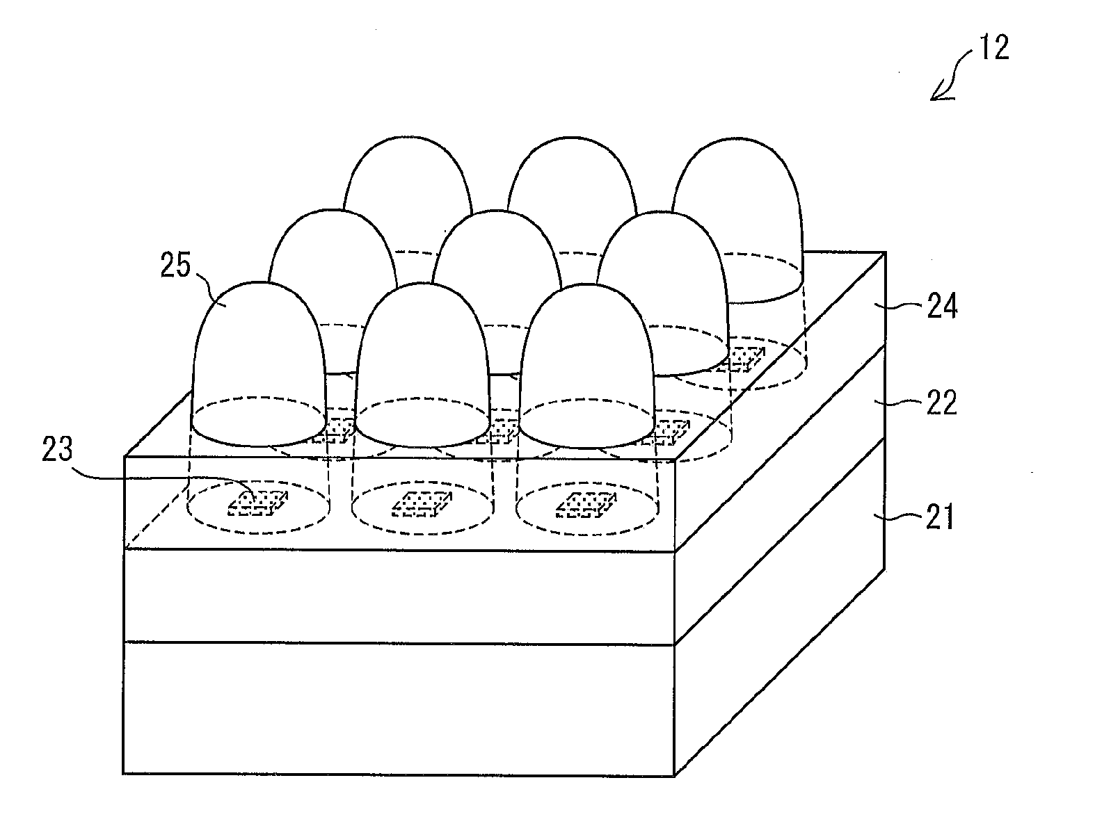
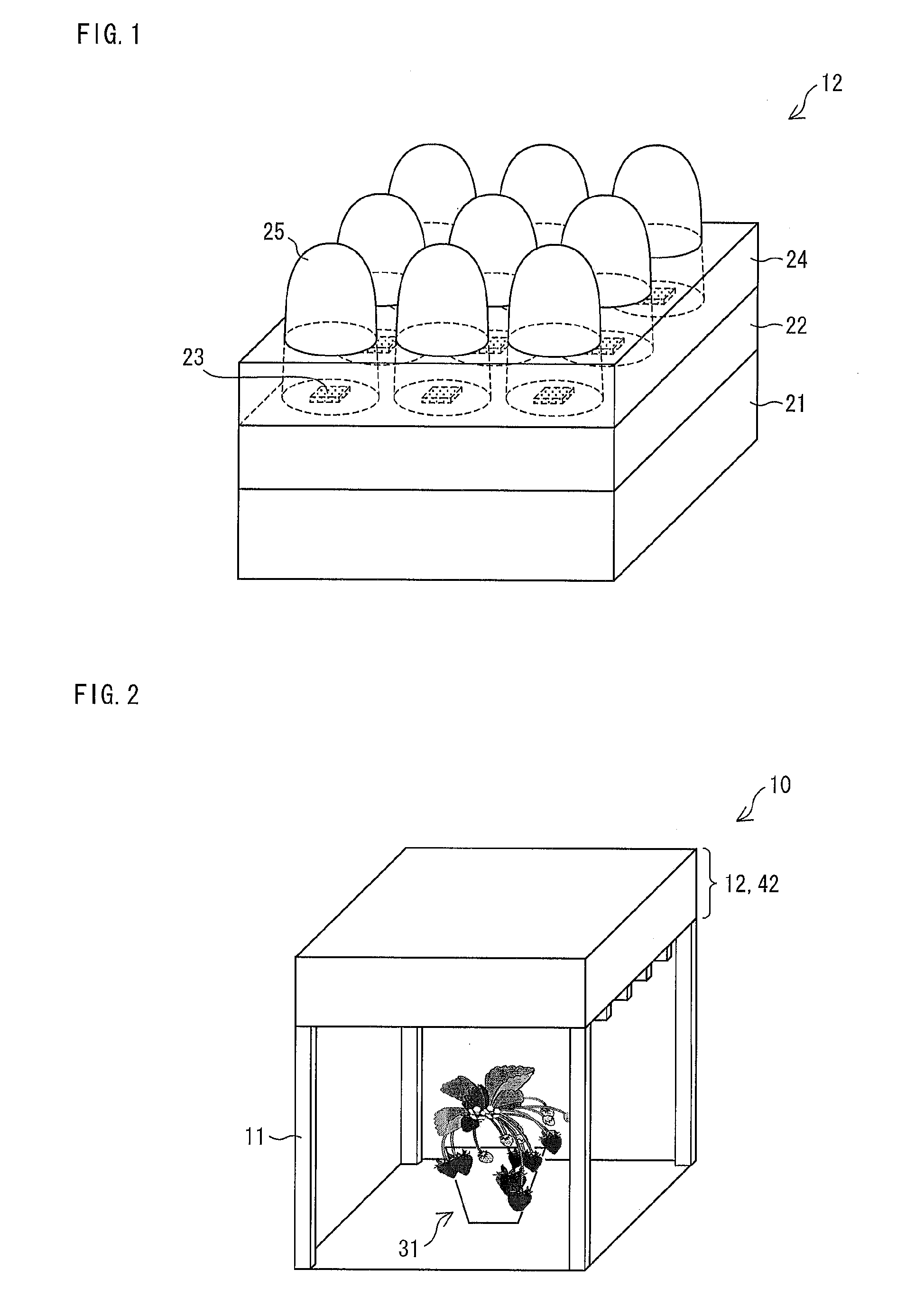
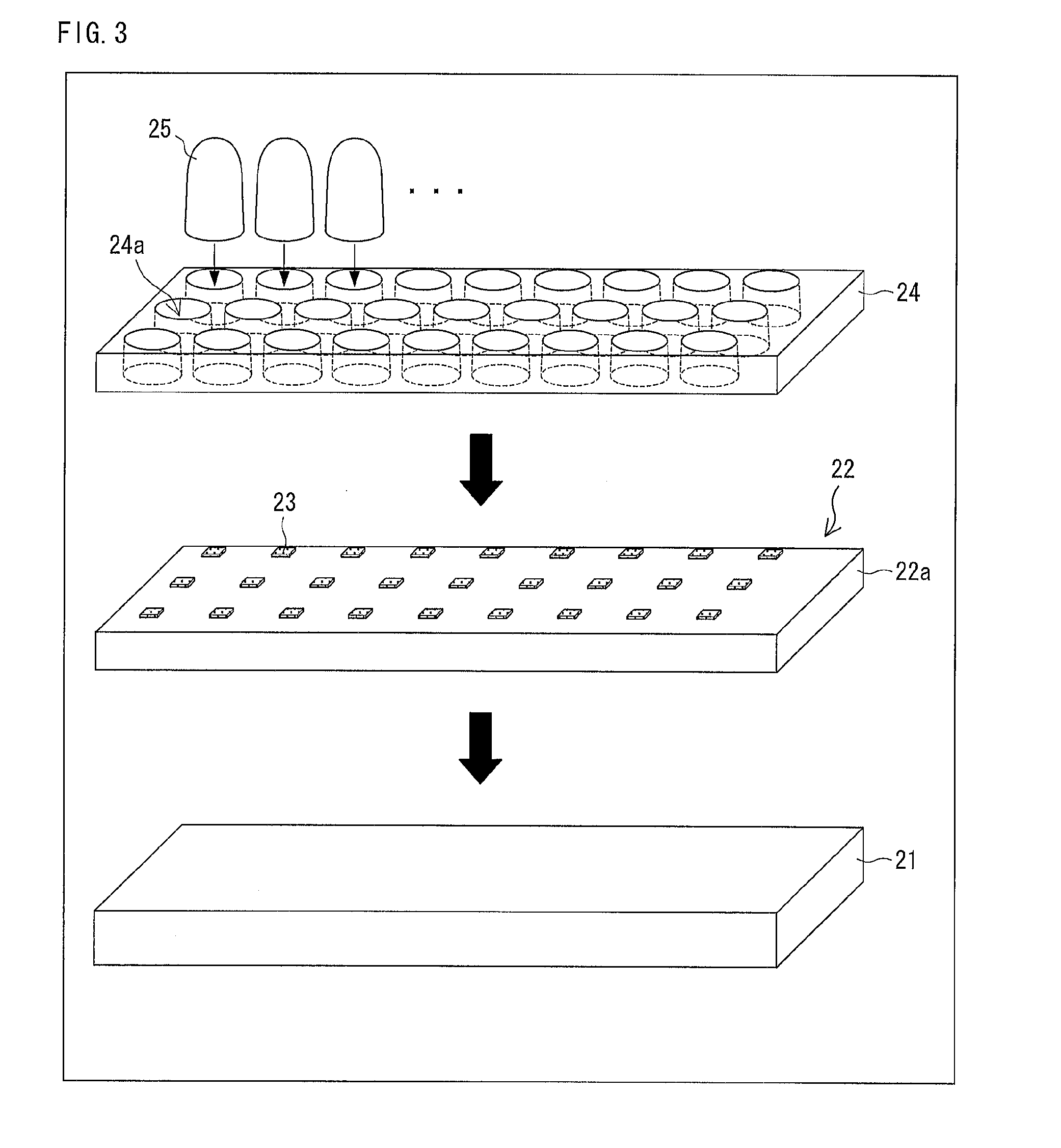
[0039]FIG. 2 illustrates the external appearance of a plant cultivation apparatus 10 in accordance with the present embodiment. As illustrated in FIG. 2, the plant cultivation apparatus 10 is constituted by a case 11 in the shape of a cube and an illumination apparatus 12 provided on the top face of the case 11. In the plant cultivation apparatus 10, a plant 31 is placed on the bottom face of the case 11, and is irradiated with light from the illumination apparatus 12 provided on the top face. The shape of the case 11 is not limited to a cube a...

embodiment 2

[0084]The following description discusses a second embodiment of the present invention. A plant cultivation apparatus 10 of the present embodiment is different in the configuration of an illumination apparatus from Embodiment 1. In view of this, the present embodiment describes only the differences between the present embodiment and Embodiment 1. Constituents not especially described here can have the same configurations as those of Embodiment 1.

[0085]The external appearance of the plant cultivation apparatus 10 in accordance with the present embodiment is illustrated in FIG. 2. The plant cultivation apparatus 10 includes an illumination apparatus 42 in accordance with the present embodiment.

[0086](Configuration of Illumination Apparatus)

[0087]The following description discusses a specific configuration of the illumination apparatus 42 in accordance with the present embodiment. FIG. 10 is a perspective view of the illumination apparatus 42. In FIG. 10, the illumination apparatus 42,...


PUM


Abstract

An illumination apparatus (12) of the present invention is an illumination apparatus for irradiating a plant with light. The illumination apparatus (12) includes a light-emitting diodes (23) serving as light sources; an LED substrate (22) on which the light-emitting diodes (23) are provided; a lens (25) (an optical member) provided between the LED substrate (22) and the plant to be irradiated, the lens (25) changing the paths of light emitted from the light-emitting diodes (23); and a lens holding plate (24) (an optical member) to hold the lens (25). The lens (25) is removably attached to the apparatus. With this configuration, it is possible to provide an illumination apparatus for cultivating plants, which illumination apparatus has been improved from the viewpoint of control of heat generated by an LED and control of light distribution of the LED.

Description

TECHNICAL FIELD[0001]The present invention relates to an illumination apparatus for cultivating plants and a plant cultivation apparatus including the illumination apparatus.BACKGROUND ART[0002]Illumination apparatuses using light-emitting diodes (LED) as light sources have been used in various fields recently. For example, there has been proposed the use of LED illumination apparatuses as artificial light sources for plant factories or plant cultivation apparatuses for cultivating plants such as vegetables indoors.[0003]LEDs are very advantageous as light sources for plant cultivation, for the following reasons. The LEDs are efficient as light sources for plants because only light having wavelengths necessary for plants can be selected. In addition, the LEDs do not contain any infrared rays or heat rays, which are contained in a large amount in conventional light sources such as incandescent lamps, fluorescent lamps, metal halide lamps, and high-pressure sodium lamps. That is, conv...

Claims


Application Information

Patent Timeline
IPC IPC(8): F21V11/00
CPCA01G7/045A01G9/26F21V5/007F21V17/002F21Y2101/02F21Y2105/001F21V17/12F21Y2105/10F21Y2115/10A01G9/249Y02A40/25Y02P60/14
Inventor KUBO, TOMOKI
Owner SHARP KK
Why Eureka
Try Eureka