
Real time monitoring of computer for determining speed and energy consumption of various processes

Active Publication Date: 2013-01-24
ATERNITY LLC
View PDF25 Cites 125 Cited by
  • Summary
  • Abstract
  • Description
  • Claims
  • Application Information

AI Technical Summary

Benefits of technology

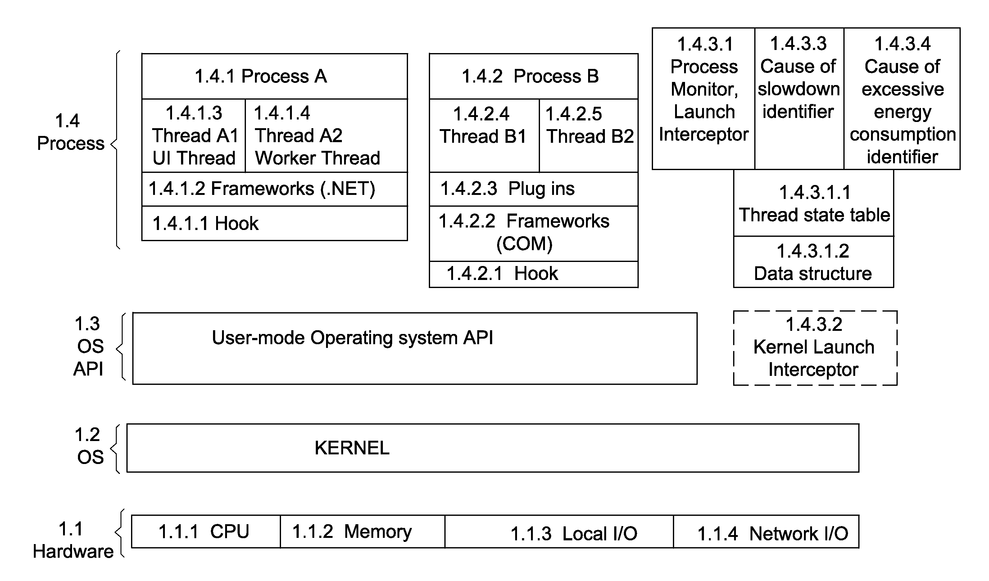
The patent describes a system for identifying the causes of slow downs in a computer system caused by certain processes. The system monitors the performance of threads in these processes and detects when there is a delay in the system. By analyzing the performance data and identifying the functions that are causing the delay, the system can identify the cause and take appropriate action to fix the problem. The system can also use hooking of voluntary API calls to collect the performance information. The system can normalize the performance data with respect to time and can also identify the modules that are causing the delay. The technical effect of the system is to improve the performance and efficiency of computer systems by identifying and fixing the causes of slow downs.

Problems solved by technology

One of the primary problems of the PC (computer) world today in general and Microsoft specifically is that component and multi-tasking Operating Systems such as Microsoft Windows, out of the box, operates relatively fast.
Other problems include intermittent slow down of PCs resulting from environmental or other conditions that cause a slow down.
Source and object-code based profilers used by application developers slow the applications down significantly and thus are not appropriate for running within performance sensitive operating environments, such as the ones in use by every day users.
There is no system today that can be used while users are actually using the operating system and applications to determine what the cause of the slowdown is.

Method used


Image

  • Real time monitoring of computer for determining speed and energy consumption of various processes
  • Real time monitoring of computer for determining speed and energy consumption of various processes
  • Real time monitoring of computer for determining speed and energy consumption of various processes

Examples


Embodiment Construction

[0036]Reference will now be made in detail to embodiments of the present invention, examples of which are illustrated in the accompanying drawings, wherein like reference numerals refer to the like elements throughout. The embodiments are described below to explain the present invention by referring to the figures.

[0037]Although the following text sets forth a detailed description of at least one embodiment or implementation, it is to be understood that the legal scope of protection of this application is defined by the words of the claims set forth at the end of this disclosure. The detailed description is to be construed as exemplary only and does not describe every possible embodiment since describing every possible embodiment would be impractical, if not impossible. Numerous alternative embodiments and / or implementations are both contemplated and possible, using either current technology or technology developed after the filing date of this patent, which would still fall within ...


PUM


Abstract

The presently disclosed subject matter includes a system and method which enable to identify one or more causes for excessive energy consumption in a computer executing one or more processes. Information indicating that consumption of a computer-resource of at least one of said processes is greater than a predefined threshold is obtained and one or more threads of said at least one process which are in running state are identified. Thread performance information of at least one thread in running state is collected and used for identifying one or more functions that are the cause for said state of the respective thread. The identified functions are associated with their respective modules in order to identify one or more modules of said process, which are the cause for said excessive energy consumption.

Description

CROSS REFERENCE TO RELATED APPLICATIONS [0001]This Application is a continuation-in-part of application Ser. No. 12 / 608,451, filed Oct. 29, 2009, which was a non-provisional of U.S. Provisional Application 61 / 109,419, filed on Oct. 29, 2008, the entireties of which are incorporated herein by reference thereto.BACKGROUND [0002]1. Technical Field[0003]Embodiments of this invention relate to determining the cause of the slowdown of a computer and particularly to the cause of the slowdown of a computer while the computer is running.[0004]2. Description of Related Art[0005]One of the primary problems of the PC (computer) world today in general and Microsoft specifically is that component and multi-tasking Operating Systems such as Microsoft Windows, out of the box, operates relatively fast. But after a few months, as additional applications and extension modules (e.g. ActiveX, OLE Controls, Plug-ins, Filters, etc.) are installed to run on the computer the computer slows down. Other probl...

Claims


Application Information

Patent Timeline
IPC IPC(8): G06F11/36
CPCG06F11/0715G06F11/079G06F11/3409G06F11/3466Y02B60/165G06F2201/875G06F2201/88G06F11/3612G06F2201/86Y02D10/00
Inventor SHOCHAT, EDENELKIND, DAVID
Owner ATERNITY LLC
Learn More