Selective power amplifier

a power amplifier and selective technology, applied in the field of selective power amplifiers, can solve the problems of not all energy provided as supply power to the power amplifier becomes signal power, consumes a certain amount of energy, and consumes a large amount of energy, so as to improve the quality of operation, reduce the impact, and reduce the effect of energy consumption

Active Publication Date: 2017-07-18
TELEFON AB LM ERICSSON (PUBL)
View PDF18 Cites 0 Cited by
  • Summary
  • Abstract
  • Description
  • Claims
  • Application Information

AI Technical Summary

Benefits of technology

[0004]An object of the invention is to at least alleviate the above stated problem. The present invention is based on the understanding that, when using a radio in communication systems allowing a multitude of transmission scenarios in sense of allowed or devised transmission properties, depending on transmission properties, and especially allocated bandwidth, the most efficient, and still feasible with regard to side effects, among polar modulation operation and envelope tracking operation of a power amplifier and closely related circuitry of the transmitter can be selected such that quality of operation is improved in sense of low energy consumption and low impact of non-desired side effects. That is, polar modulation is preferred to be used due to its relatively low energy consumption as long as side effects, such as spectral leakage, is within reasonable limits, and by this idea, the envelope tracking is used otherwise to maintain proper transmission. The power amplifier can thus be operated in non-linear, and thus energy saving, mode as much as possible, and then be operated in linear, but more energy consuming, mode when that is necessary. The allocated bandwidth is the most important factor for deciding when to use which mode, but this disclosure also provides approaches for further adaptation to the circumstances, such as considering modulation type, output power, error vector magnitude and / or spectral leakage requirement for the transmission to be made by the transmitter, wherein energy consumption can be held down when any possibility for that is given by the transmission properties.

Problems solved by technology

Most energy is consumed when transmitting, and a power amplifier, having its task to provide the radio power to antenna, will of course consume some amount of energy.
However, not all energy provided as supply power to the power amplifier becomes signal power for the radio signal.

Method used


Image

  • Selective power amplifier
  • Selective power amplifier
  • Selective power amplifier

Examples


Embodiment Construction

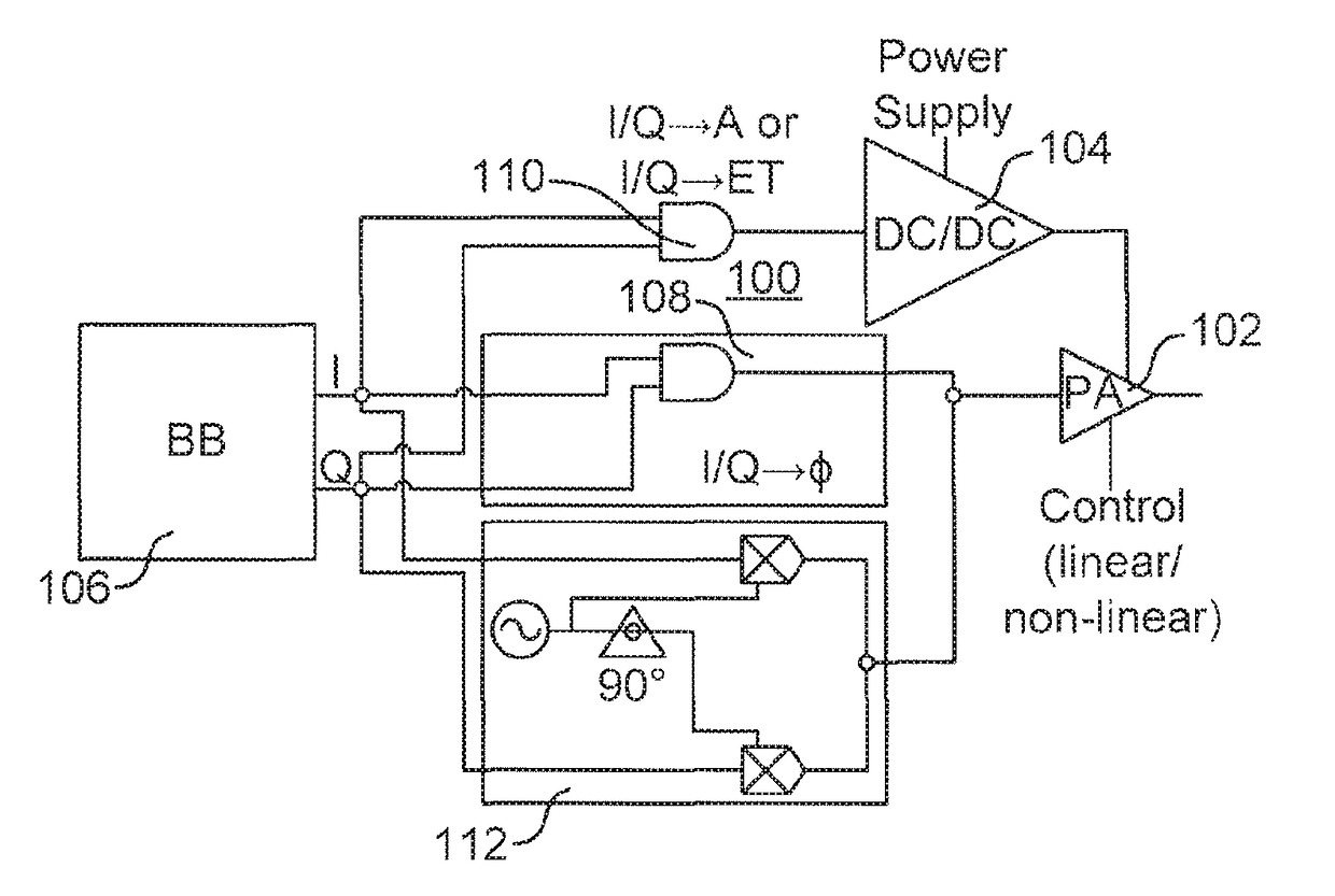
[0054]For the understanding of this disclosure, the reader should be aware that polar modulation enables use of a nonlinear power amplifier (PA), which is power efficient, but implies bandwidth expansion issues. Using polar modulation is thus not suitable for wide bandwidth applications like wide band 3GPP LTE where bandwidths of 20 MHz can be used. A linear PA with a constant supply voltage does not imply such bandwidth expansion issues, but is significantly less power efficient than a non-linear PA. The linear PA can be made more power efficient by using envelope tracking. Envelope tracking requires use of a linear PA, which is inherently less power efficient than the non-linear PA, but is still more efficient than a PA without envelope tracking, i.e., a constant supply voltage driven PA. High power efficiency implies that more radio power is provided to the antenna and / or less heat is created by the power amplifier at a given supply power.

[0055]FIG. 1 illustrates a transmitter ci...


PUM


Abstract

A transmitter comprising a power amplifier, a phase modulator, a switched DC-DC converter, all operating in dual mode, and a controller is disclosed. The power amplifier is arranged to selectively operate either in a first mode or in a second mode, wherein the first mode is a linear mode and the second mode is a non-linear mode in order to save power with least increasing cost in hardware. The transmitter is adapted to operate at different allocated bandwidths, for different radio standards while keeping minimum power consumption governed by the controller. A transceiver, a communication device, a method and a computer program are also disclosed.

Description

RELATED APPLICATIONS[0001]This application is a continuation of co-pending U.S. patent application Ser. No. 14 / 366,542, filed 18 Jun. 2014, which is a national stage entry under 35 U.S.C. §371 of international patent application serial no. PCT / SE2012 / 051345, filed 5 Dec. 2012, which claims priority to and the benefit of U.S. provisional patent application Ser. No. 61 / 582,541, filed 3 Jan. 2012, as well as EP application 11194588.7 filed 20 Dec. 2011. The entire contents of each of the aforementioned applications is incorporated herein by reference.TECHNICAL FIELD[0002]The present invention generally relates to a transmitter arranged to operate in different modes depending on allocated bandwidth of transmission, and to a corresponding transceiver, communication device, method and computer program.BACKGROUND[0003]Reduction of energy consumption in radio devices is always desired, and particularly for radio devices that rely on battery. Most energy is consumed when transmitting, and a ...

Claims


Application Information

Patent Timeline
Patent Type & Authority Patents(United States)
IPC IPC(8): G08C17/00H03F1/32H04L12/741H04L12/26H04L27/36H04L1/20H04J11/00H04W72/04H03F3/24H03F1/02H04B1/403H04B1/04H04W52/52H04W88/12H04L45/74
CPCH04W52/52H03F1/0211H03F1/0222H03F1/3282H03F3/245H04B1/04H04B1/406H04J11/00H04L1/203H04L27/362H04L43/16H04L45/745H04W72/042H04W72/0406H04W72/0413H04W72/0453H04W72/0473H03F2200/102H03F2200/336H03F2201/3212H04B2001/045H04W88/12H03G5/28H03F1/02H03F3/24H03F1/0227H03F3/19H03F2200/451H04W52/0209Y02D30/70H04W72/20H04W72/21H04W72/23H03F3/217H04L27/0008
Inventor MU, FENGHAOLINDOFF, BENGT
Owner TELEFON AB LM ERICSSON (PUBL)
Why Eureka
Try Eureka