Touch system for preventing water influence

Active Publication Date: 2018-09-06
ADVANCED ANALOG TECH INC
View PDF2 Cites 1 Cited by
  • Summary
  • Abstract
  • Description
  • Claims
  • Application Information

AI Technical Summary

Benefits of technology

The present invention provides a touch system that can prevent water influence and determine whether or not the touch is valid by applying equipotentials or division voltages. This system can erase the capacitance effect resulted from the ion-contained liquid and avoid mis-touch at the IC chip, thereby improving the operability of the touch system.

Problems solved by technology

In view of current technology, while a water drop falls right at a touch pad, the IC chip may not be able to judge if the touch upon the touch pad is made by a human or a raindrop.
Therefore, it is a problem of the current electronic device that the conventional touch pads would lead to excessive energy consumption and unnecessary machine operation.

Method used


Image

  • Touch system for preventing water influence
  • Touch system for preventing water influence
  • Touch system for preventing water influence

Examples


first embodiment

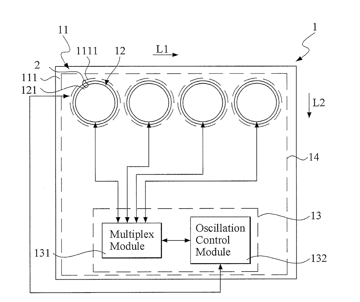
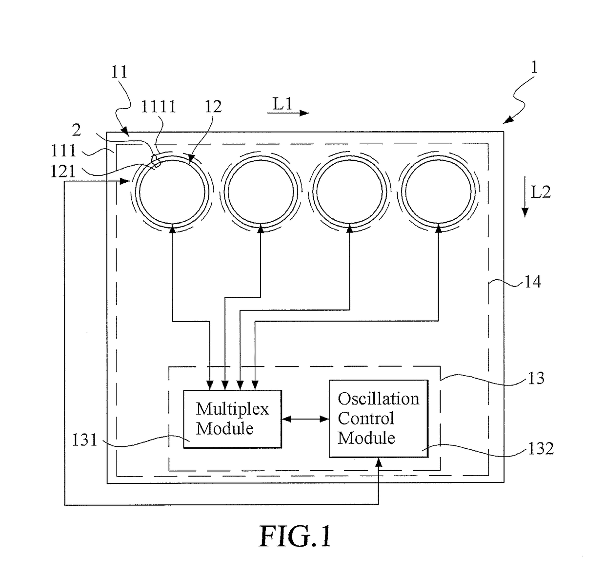
[0029]In addition, it shall be noted that this first embodiment of the present invention adopts the capacitor-type touch control. Hence, if the ion-contained liquid 2 on the insulation board 14 can be positioned properly between the conductive board body 111 and the respective touch portion 121 of one of the touch pads 12, then a corresponding capacitance effect would be induced between the conductive board body 111 and the respective touch portion 121 of one of the touch pads 12.

[0030]Refer now to FIG. 3 and FIG. 4; where FIG. 3 is a schematic view of a second embodiment of the touch system for preventing water influence in accordance with the present invention, and FIG. 4 is a schematic view of a circuit for the second embodiment of FIG. 3. As shown, the second embodiment of the touch system 1a is configured for preventing water influence, and includes a circuit board 11a, a plurality of touch pads 12a and 12b, a control chip 13a and an insulation board 14a. In this embodiment, si...

second embodiment

[0038]The control module 134a, electrically coupled with the multiplex module 132a and the first node 1331a of the capacitor 133a, is set to have a voltage difference-judged value and a ratio judged value, and can be an existing micro processing unit. Hence, in this second embodiment, the output of the voltage oscillation wave to the conductive board body 111a for erasing the capacitance effect by equipotentials does not go through the oscillator anymore, but judges directly by adopting the charge distribution.

[0039]The insulation board 14a, covering at least part of the conductive board body 111a, can be, but not limited to, an acrylic board or a glass board.

[0040]In practice, the control module 134a bases on a scan time to conduct alternately the multiplex module 132a and each of the touch portions 121a, 121a′, 121a″, 121a′″, 121b, 121b′, 121b″ and 121b′″ of any one of the plurality of touch pads 12a and 12b, such that the work voltage can go through the touch-pad capacitor C1 and...


PUM


Abstract

A touch system includes a circuit board, touch pads, a control chip and an insulation board. The circuit board has a conductive board body including configuration regions. The touch pads is spaced from the configuration regions by the conductive board body. Each touch pad includes at least one touch portion. The control chip includes a multiplex module coupling the touch pads and an oscillation control module coupling the conductive board body. The oscillation control module conducts alternately the multiplex module and every touch portions to utilize a work voltage for generating a voltage oscillation wave respective to each conducted touch portion. The voltage oscillation wave is transmitted to the conductive board body. When an ion-contained liquid is on the insulation board by covering partly the conductive board body and the touch portion, a capacitance effect therebetween is forming by the work voltage, but further erased by the voltage oscillation wave.

Description

[0001]This application claims the benefit of Taiwan Patent Application Serial No. 106107035, filed Mar. 3, 2017, the subject matter of which is incorporated herein by reference.BACKGROUND OF THE INVENTION1. Field of the Invention[0002]The invention relates to a touch system for preventing water influence, and more particularly to the touch system for preventing water influence that applies equipotentials to avoid capacitance effect or uses division voltages to judge if or not the instant touch is valid.2. Description of the Prior Art[0003]As the technology progresses rapidly, prosperity of networking has made people's daily life filled with various electronic devices, such as washing machines, microwaves, outdoor coded locks and the like electronic devices. In particular, most of these electronic devices are improved to adopt touch-keys. Generally speaking, the touch-keys are formed by constructing a plurality of touch pads on a printed circuit board (PCB) so as thereby to account f...

Claims


Application Information

Patent Timeline
IPC IPC(8): G06F3/041G06F3/044
CPCG06F3/044G06F3/0418G06F3/0443G06F2203/04107H03K17/9622H03K2217/960705
Inventor LEE, KUN-HSU
Owner ADVANCED ANALOG TECH INC
Why Eureka
Try Eureka