Electric booster
- Summary
- Abstract
- Description
- Claims
- Application Information
AI Technical Summary
Benefits of technology
Problems solved by technology
Method used
Image
Examples
first embodiment
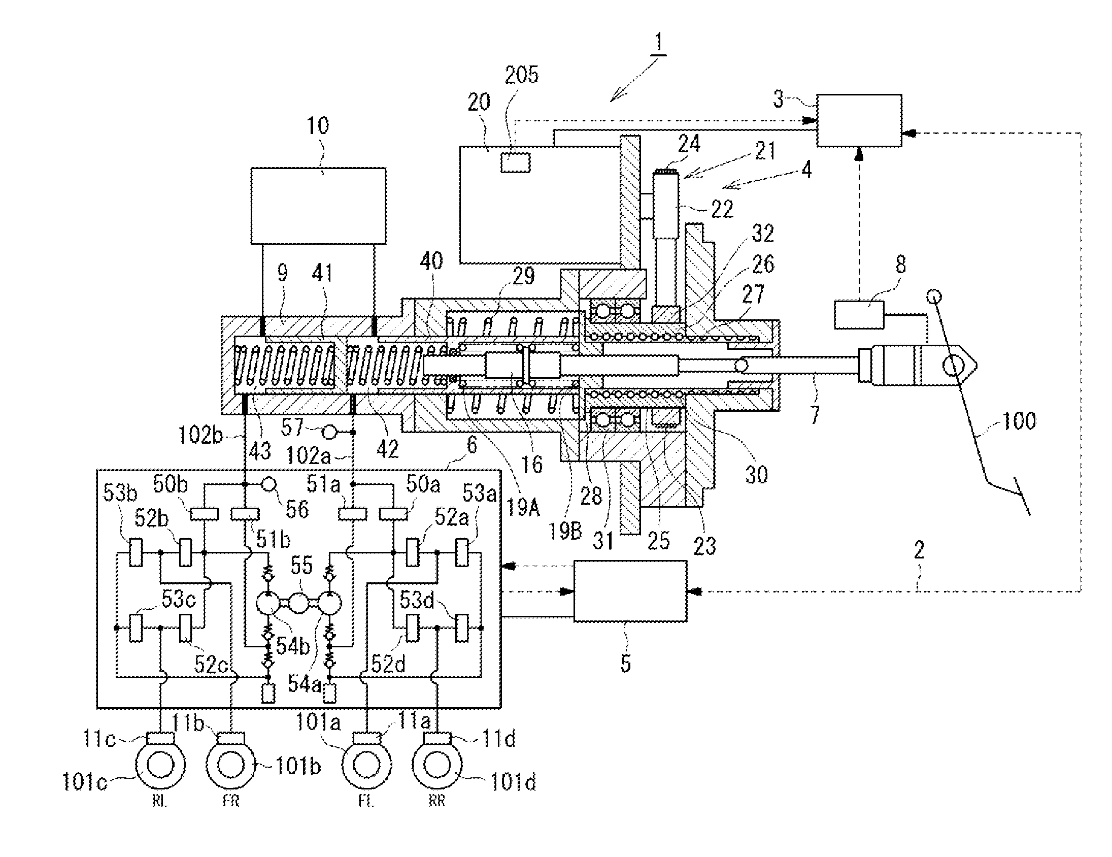
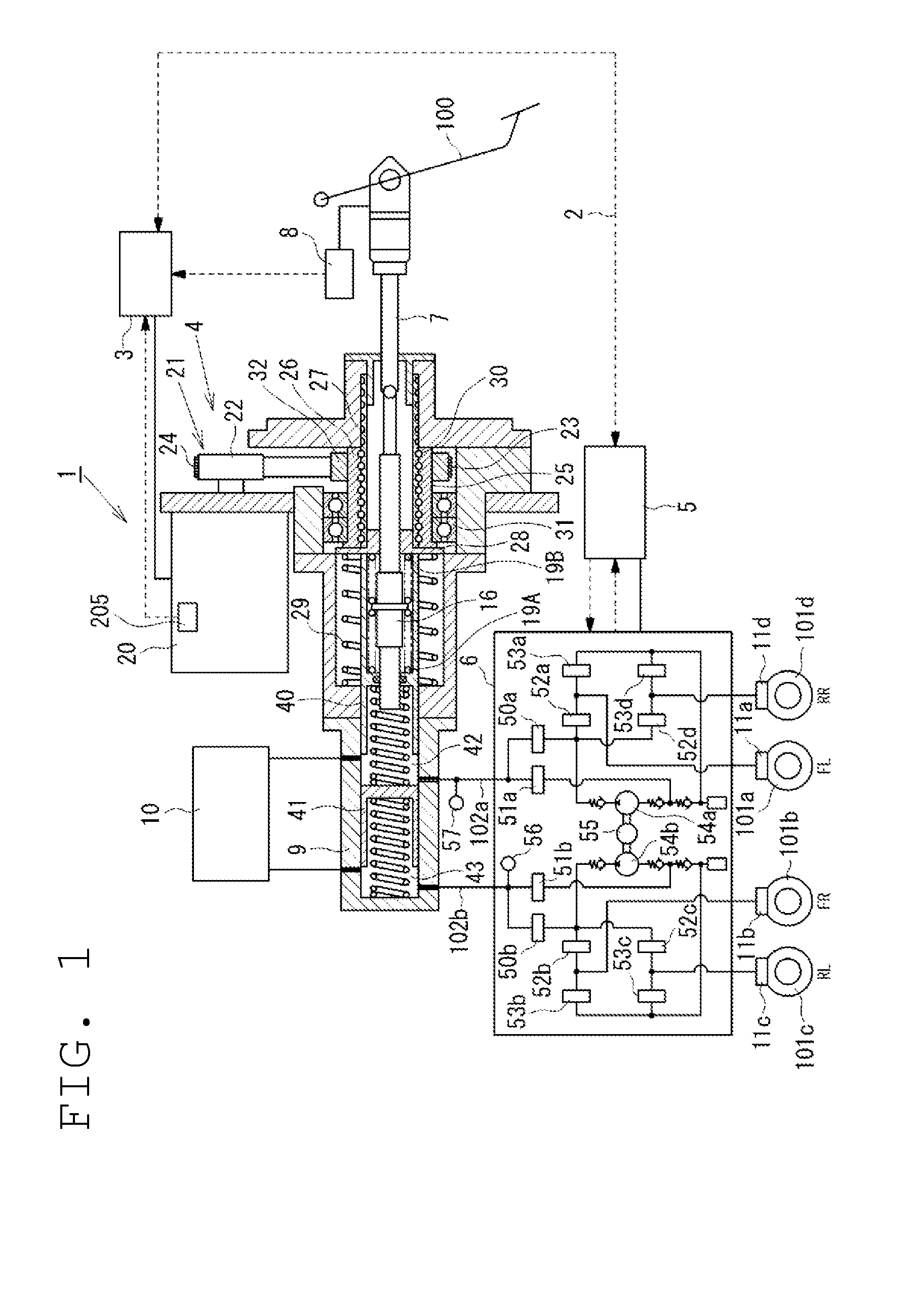
[0085]As the first embodiment, processing for executing the changing control for changing the ratio of the movement amount of the primary piston 40 to the movement amount of the input rod 7 in accordance with whether or not the movement amount (stroke) of the input rod 7, which is used as the control changing input I2, is equal to or larger than the threshold value is described referring to FIGS. 5 and 6.
[0086]Referring to FIG. 5, in Step S21, it is determined whether or not the movement amount of the input rod 7 is equal to or larger than the threshold value. When the movement amount of the input rod 7 is smaller than the predetermined threshold value, the target position (movement amount) of the primary piston 40 is determined so that the ratio of the movement amount of the primary piston 40 to the movement amount of the input rod 7 becomes equal to the predetermined first ratio in Step S22. On the other hand, when the movement amount of the input rod 7 is equal to or larger than ...
second embodiment
[0094]Next, as the second embodiment, processing for changing the ratio of the movement amount of the primary piston 40 to the movement amount of the input rod 7 in accordance with whether or not the brake fluid pressure in the master cylinder 9, which is used as the control changing input I2, is equal to or larger than the threshold value, is described referring to FIGS. 7 and 8.
[0095]Referring to FIG. 7, in Step S41, it is determined whether or not the brake fluid pressure in the master cylinder 9 is equal to or larger than the threshold value. When the brake fluid pressure in the master cylinder 9 is smaller than the threshold value, the target position of the primary piston 40 is determined so that the ratio of the movement amount of the primary piston 40 to the movement amount of the input rod 7 becomes equal to the first ratio in Step S42. On the other hand, when the brake fluid pressure in the master cylinder 9 is equal to or larger than the threshold value, the target positi...
third embodiment
[0103]Next, as a third embodiment, processing for changing the ratio of the movement amount of the primary piston 40 to the movement amount of the input rod 7 in accordance with whether or not the pedaling force applied by the driver on the brake pedal 100, which is used as the control changing input I2, is equal to or larger than a predetermined threshold value, is described referring to FIG. 9.
[0104]Referring to FIG. 9, in Step S61, it is determined whether or not the pedaling force applied by the driver on the brake pedal 100 is equal to or larger than the threshold value. When the pedaling force is smaller than the threshold value, the target position of the primary piston 40 is determined so that the ratio of the movement amount of the primary piston 40 to the movement amount of the input rod 7 becomes equal to the first ratio in Step S62. On the other hand, when the pedaling force is equal to or larger than the threshold value, the target position of the primary piston 40 is d...
PUM
 Abstract
Description
Claims
Application Information
 - R&D
- Intellectual Property
- Life Sciences
- Materials
- Tech Scout
- Unparalleled Data Quality
- Higher Quality Content
- 60% Fewer Hallucinations
Browse by: Latest US Patents, China's latest patents, Technical Efficacy Thesaurus, Application Domain, Technology Topic, Popular Technical Reports.
© 2025 PatSnap. All rights reserved.Legal|Privacy policy|Modern Slavery Act Transparency Statement|Sitemap|About US| Contact US: help@patsnap.com


