Hydraulic Circuit Structure of Work Vehicle

Active Publication Date: 2009-03-26
YANMAR POWER TECHNOLOGY CO LTD
View PDF7 Cites 3 Cited by
  • Summary
  • Abstract
  • Description
  • Claims
  • Application Information

AI Technical Summary

Benefits of technology

[0023]With the hydraulic circuit structure of the work vehicle according to the first aspect of the invention, it is possible to actuate the respective stabilizer cylinders irrespective of the load and speedy attitude control of the machine becomes possible.
[0024]Moreover, the pressure oil of the pump connected to the boom and the bucket is supplied to the arm control valve section by switching the selector valve in the position on the upstream side of the check valve and for selecting connection to or disconnection from the tank. Therefore, it is possible to actuate the arm when it is operated simultaneously with the swing.
[0025]With the hydraulic circuit structure of the work vehicle according to the second aspect of the invention, by allowing a sur

Problems solved by technology

However, in a machine attitude control in back hoe operation, pressure oil is preferentially fed to light-loaded machines and some work machi

Method used


Image

  • Hydraulic Circuit Structure of Work Vehicle
  • Hydraulic Circuit Structure of Work Vehicle
  • Hydraulic Circuit Structure of Work Vehicle

Examples


embodiment 1

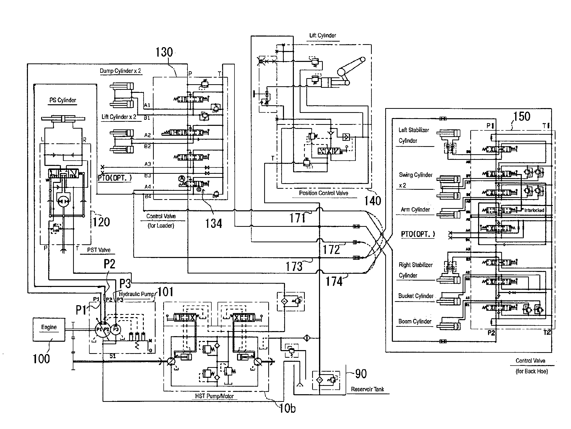
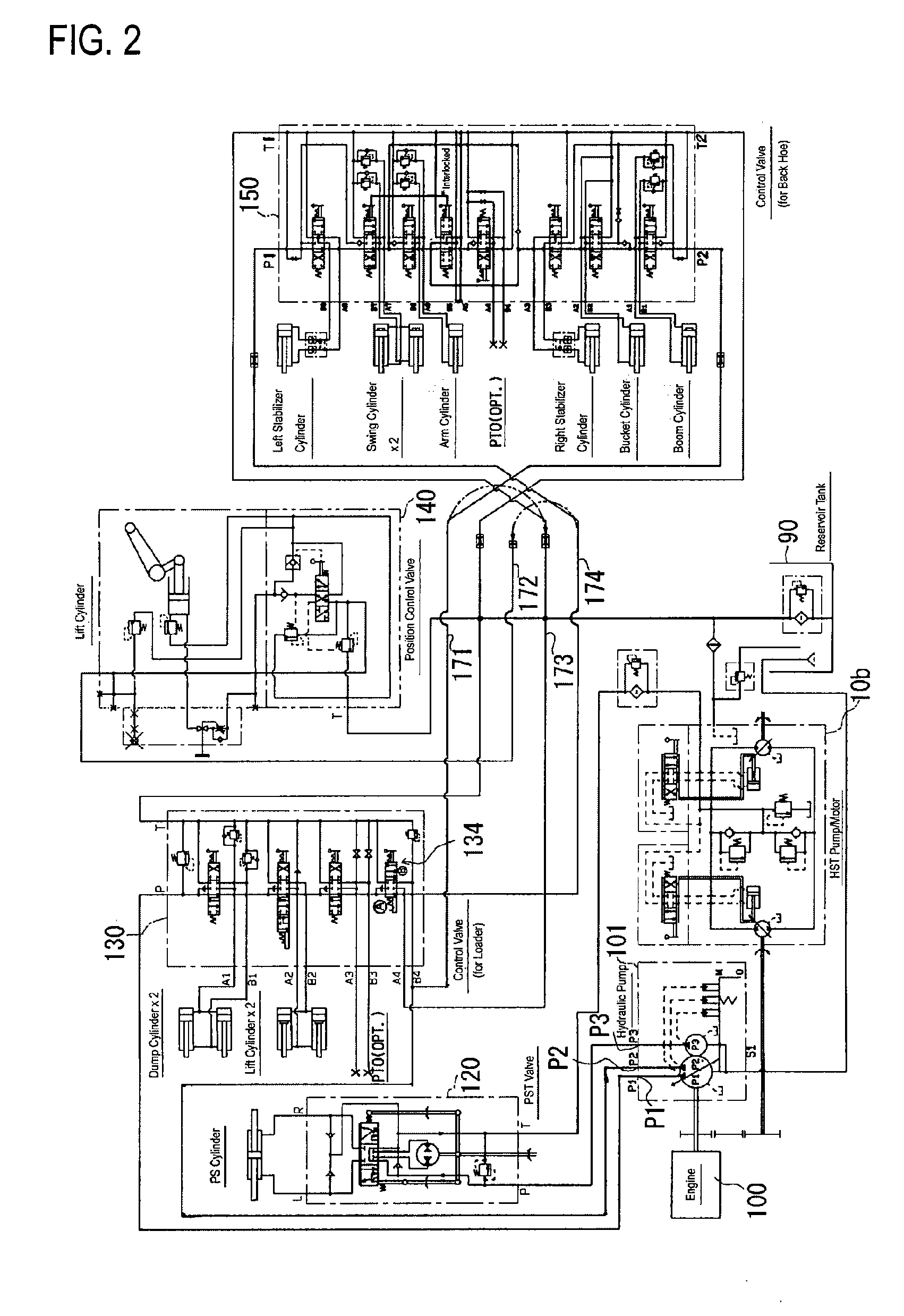
[0057][Overall Structure]

[0058]A work vehicle according to an embodiment of the present invention will be described.

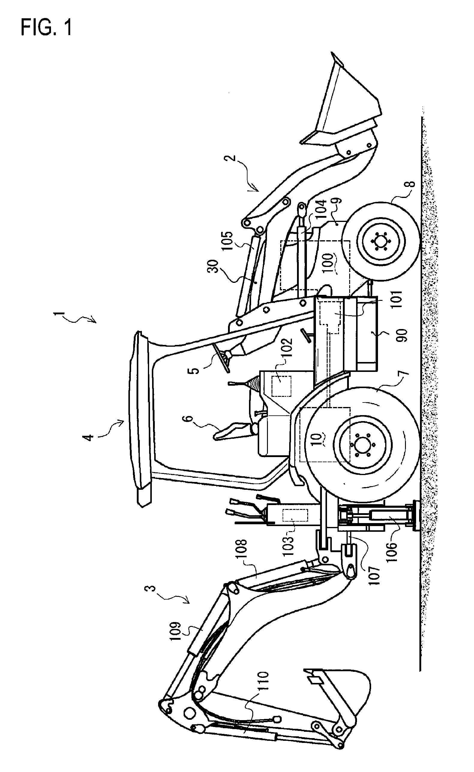
[0059]FIG. 1 is a general side view of the work vehicle.

[0060]The work vehicle 1 shown in FIG. 1 is a tractor loader back hoe and is mounted with a loader 2 and a drilling device 3. A control section 4 is provided at a center, the loader 2 is disposed at the front, and the drilling device 3 is disposed at the rear of the work vehicle 1. The work vehicle 1 is mounted with front wheels 8, 8 and rear wheels 7, 7 and can travel while mounted with the loader 2 and the drilling device 3.

[0061]In the control section 4, a steering wheel 5 and an operator's seat 6 are disposed. Travel operation devices and operation devices for the loader 2 are disposed on a side of the seat 6. Therefore, steering operation of the work vehicle 1 and operation of the loader 2 can be carried out in the control section 4.

[0062]The loader 2 as a loading device is connected to side portions of the w...


PUM


Abstract

A hydraulic circuit structure of a work vehicle capable of solving a problem in a conventional structure wherein, in a machine attitude control in back hoe operation, pressure oil is preferentially fed to light-loaded machines and some work machines are slowly moved or stopped and, accordingly, the attitudes of the machines cannot be rapidly controlled and work performance is affected. To solve this problem, the hydraulic circuit of the work vehicle comprises two valve groups for loader and back hoe having circuits to supply the pressure oil from one hydraulic pump P1 to a valve group 150 for back hoe control through a valve group 130 for loader control and the pressure oil from the other hydraulic pump P2 directly to the valve group 150 for back hoe control. The pressure oil is independently supplied from the hydraulic pumps P1 and P2 to valve sections 152 for controlling right and left stabilizer cylinders installed in the valve group 150 for back hoe control.

Description

TECHNICAL FIELD[0001]The present invention relates to a hydraulic circuit structure of a work vehicle and more specifically to a hydraulic circuit structure for efficient driving of hydraulic work machines attached to a work vehicle.BACKGROUND ART[0002]Conventionally, a work vehicle such as a back hoe loader is equipped with a plurality of hydraulic systems and hydraulic oil is supplied by one hydraulic pump. Work machines and the hydraulic pump are connected in parallel (e.g., refer to Patent Document 1).[0003][Patent Document 1] Japanese Patent Application Laid-Open No. 2001-49687DISCLOSURE OF THE INVENTION[0004]Problem to Be Solved[0005]However, in a machine attitude control in back hoe operation, pressure oil is preferentially fed to light-loaded machines and some work machines are slowly moved or stopped and, accordingly, the attitudes of the machines cannot be rapidly controlled and work performance is affected.Solution[0006]To solve the above problem, the present invention ta...

Claims


Application Information

Patent Timeline
IPC IPC(8): F15B11/17F15B11/00
CPCE02F9/2239E02F9/2292F15B11/16F15B11/17F15B2211/7053F15B2211/20546F15B2211/20576F15B2211/3116F15B2211/20523
Inventor YAMASHITA, MASAAKI
Owner YANMAR POWER TECHNOLOGY CO LTD
Why Eureka
Try Eureka