Tube compression fitting and flared fitting used with connection body and method of making same

a compression fitting and connection body technology, applied in the direction of pipe joints, pipes/joints/fittings, mechanical devices, etc., can solve the problems of difficulty in explaining the reason for the problem, the difficulty of matching tolerances, and the complexity of matching tolerances, so as to increase the surface hardness of the sleeve, the effect of sufficient lubricity

Inactive Publication Date: 2013-01-31
PARKER HANNIFIN CORP
View PDF11 Cites 11 Cited by
  • Summary
  • Abstract
  • Description
  • Claims
  • Application Information

AI Technical Summary

Benefits of technology

[0028]The invention includes a forming operation and deforms (extrudes) the tubing material into the desired shape and requires a high force to flare the tubing wall. The invention employs a sleeve wherein the wall thickness of the sleeve is relatively thick and the overall length is relatively short to increase resistance of the sleeve to buckling. The angle formed between the non-biting end of the sleeve and the gland is 30 degrees instead of some designs employing 45 degrees from horizontal to eliminate deformation of the gland material outward from the axis of the flared joint. The invention uses both a mechanical bite (compression fitting) and a flared tube end (flared fitting).
[0030]In the creation of the fitting, the die is forced upward by a hydraulic cylinder toward the cap which is held in place with a threaded interconnection in the housing. The die engages the sleeve on a taper which in turn causes the sleeve to engage the gland on a taper. As the die continues to move upwardly the sleeve is prevented from collapsing outwardly as the gland supports the sleeve and is held in place by the cap. Initially, and before the die begins moving upwardly, the tubing rests on the tube engaging surface of the frusto-conical portion of the die and is slidably moveable within the sleeve and the gland against the force of gravity and can be moved freely upwardly.
[0031]As the die is moved upwardly, the sleeve is compressed against the gland by the die. The sleeve includes an extended lip portion (overhanging nose) with a radius that prevents the hardened surface of the sleeve (i.e. coated with an XADC-Armoloy® coating from damaging the tapered surface of the die.) XADC-Armoloy® is a trademark of Armoloy Corporation. Use of XADC-Armoloy® creates a hardened surface while maintaining sufficient lubricity. Before the die begins its upward movement under the force of the hydraulic screw piston, a cavity exists between the extended lip portion of the sleeve and the tube. The tapered exterior surfaces of the sleeve are deformed to substantially match the sleeve engaging tapered inner wall surface of the die. At the same time the biting edge of the sleeve begins to penetrate the tube surface forcing the inside corner of the tube against the sleeve engaging taper of the frusto-conically shaped portion of the die. A relief in the sleeve and use of the XADC-Armoloy® coating on the exterior surface of the sleeve (which increases the surface hardness of the sleeve) in combination ensures that the annular biting edge of the sleeve penetrates the tube.
[0034]The flare connection assembly includes the steps of inserting the tube and sleeve into the connection opening. Then the gland is threaded in and tightened by hand. The bottom of the connection opening has a surfaces formed in frusto-conical shape which seal on the inside of the tubing flare. The angle of the flared tube end and the frusto-conical shape are dissimilar so the seal starts as an annular surface contact on the frusto-conically shaped protrusion at the base of the housing of the connection. When the gland is torqued the sleeve contacts the inward taper in the connection body causing the sleeve to grip the tube which helps the fitting resist vibration and applies a force to the deformed (raised) tubing material as the bite increases the load carried through the tube to the frusto-conically shaped protrusion at the base of the connection. This deforms the material of the tube as required to achieve the metal to metal seal. The surface of the gland has a coating to reduce friction and permit the torque required for the seal to be applied. Further torquing of the gland applies additional force to the sleeve, the tube and may increase flaring of the tube.
[0036]If the flare does not seal correctly there is a bleed hole or passageway so pressure cannot build up around the sleeve or connection threads and cause a possible failure resulting in part ejection. This also allows for a visual indication that a connection is leaking.

Problems solved by technology

One would ordinarily conclude that this relationship could not be, and it is difficult to explain the reason therefor.
Ordinarily when an attempt is made to match machine tolerances to obtain two perfect sealing areas at two longitudinally spaced tapered regions, such as shown in this invention, difficulty arises from the inability to match such tolerances.
The problem of matching tolerances becomes all the more complex when it is realized that my fitting accommodates tubing having varying tube wall thicknesses.

Method used


Image

  • Tube compression fitting and flared fitting used with connection body and method of making same
  • Tube compression fitting and flared fitting used with connection body and method of making same
  • Tube compression fitting and flared fitting used with connection body and method of making same

Examples


Embodiment Construction

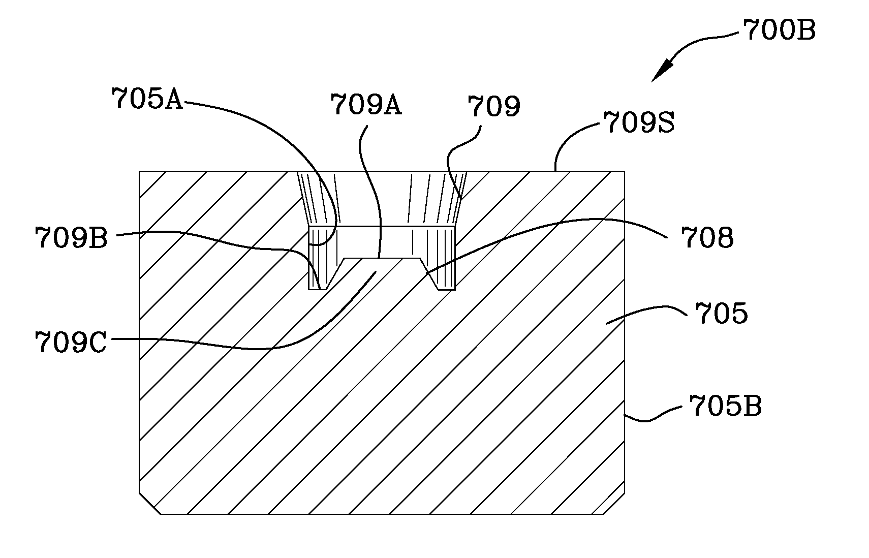
[0069]FIG. 7 is an exploded view 700 of the apparatus for making the fitting illustrating: thick walled tubing 701, interior of the tubing 701A, exterior of the tubing 701D, width of the tubing 701B and the end of tubing 701C. Gland 702 includes exterior threads on gland 702A. Gland 702 includes an inner cylindrically shaped passageway 702B through which thick walled tubing 701 passes. Cap 703 includes exterior threads 703A which mate with interior threads 706A in the aluminum housing 706. Cap 703 is rotated with a rod (not shown) inserted into cap 703. Cap 703 further includes an annular recess into which the die 705 enters. Sleeve 704 includes an inner contoured surface 704A which is generally cylindrically shaped with a relief which facilitates bending and deforming the sleeve with pressure and force applied by the gland 702 as described hereinbelow. Die 705 includes a contoured interior 705A which includes a sleeve engaging tapered surface 709 which interengages the exterior 704...


PUM

PropertyMeasurementUnit
angleaaaaaaaaaa
depthaaaaaaaaaa
lengthaaaaaaaaaa

Abstract

A high pressure tube compression fitting / flared fitting for use in combination with a thick-walled tube and a connection body wherein a sleeve is in engagement with a thick-walled tube. The sleeve is generally cylindrically shaped with the exterior thereof coated and then etched. The sleeve includes a sharp annular biting portion engaging the thick walled tube. The sleeve further includes an inner annular symmetric concavity which engages the thick-walled tube upon deformation thereof. The thick-walled tube includes a flared end portion. A gland about the thick-walled tube engages the sleeve forcing it into engagement with the frusto-conical portion of the connection body coupling the tube, tube fitting and connection body together. The flared end of the thick-walled tube interengages and seals the frusto-conical portion of the connection body.

Description

FIELD OF THE INVENTION[0001]The invention relates to a tube coupling for connecting a tube to a connection body.BACKGROUND OF THE INVENTION[0002]FIG. 1 is an enlarged side view 100 of a tube coupling disclosed in prior art U.S. Pat. No. 2,850,202 to M. F. Bauer. FIG. 2 is an enlarged and fragmentary cross-sectional view 200 of the forward end portion of the sleeve 13 shown in the prior art device illustrated in FIG. 1. FIG. 3 is a modified form 300 of the forward end portion of the sleeve 13 illustrated in the prior art device illustrated in FIG. 2. FIG. 4 is a fragmentary side view 400 of the wedge insert 20 illustrating the knurled outer surface 23 portion. FIG. 5 is a fragmentary side view 500 taken along the lines 4-4 of FIG. 2 showing principally the knurled section 23.[0003]U.S. Pat. No. 2,850,303 to M. F. Bauer, entitled Double Sealed Compression Fitting, recites, at col. 3, lns. 54 et seq. with reference to FIG. 1 thereof, “that the invention comprises generally a coupling o...

Claims


Application Information

Patent Timeline
Patent Type & Authority Applications(United States)
IPC IPC(8): B21D22/00
CPCF16L19/045Y10T29/49428F16L19/10
Inventor CIPRICH, SAMUEL D.BERNOSKY, MATTHEW T.
Owner PARKER HANNIFIN CORP
Why Eureka
Try Eureka