
Single-well diagnostics and increased oil recovery by oil injection and sequential waterflooding

a single-well, oil injection technology, applied in the direction of survey, fluid removal, borehole/well accessories, etc., can solve the problems of significant oil remaining in the reservoir, the economics of keeping the well in production may only be barely high, etc., and achieve the effect of increasing the oil recovery

Active Publication Date: 2013-01-31
UNIVERSITY OF WYOMING
View PDF18 Cites 21 Cited by
  • Summary
  • Abstract
  • Description
  • Claims
  • Application Information

AI Technical Summary

Benefits of technology

The present invention provides a method for single-well recovery of immobile residual oil from a previously waterflooded reservoir or an oil reservoir that contains immobile oil at the time of discovery. This method can be performed at various reservoir scales and can increase oil recovery from reservoirs at all stages of development, including mature reservoirs producing at high water-to-oil ratios. This method can also be used for reservoir diagnostics and can provide significant oil recovery through sequential injection of oil and brine. The effects of reservoir heterogeneity are largely cancelled when single-well procedures are employed.

Problems solved by technology

For reservoirs having been waterflooded to where the fraction of oil in the produced water is low, for example, less than 1%, keeping the well in production may only be barely economical.
However, significant quantities of oil remain in the reservoirs after primary and secondary recovery.

Method used


Image

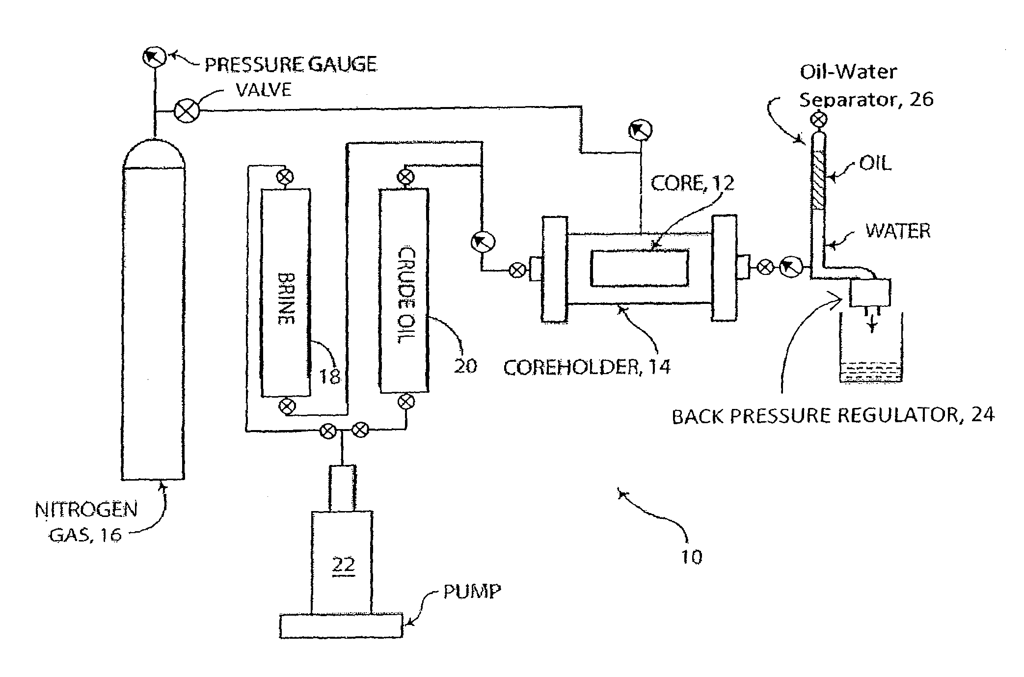
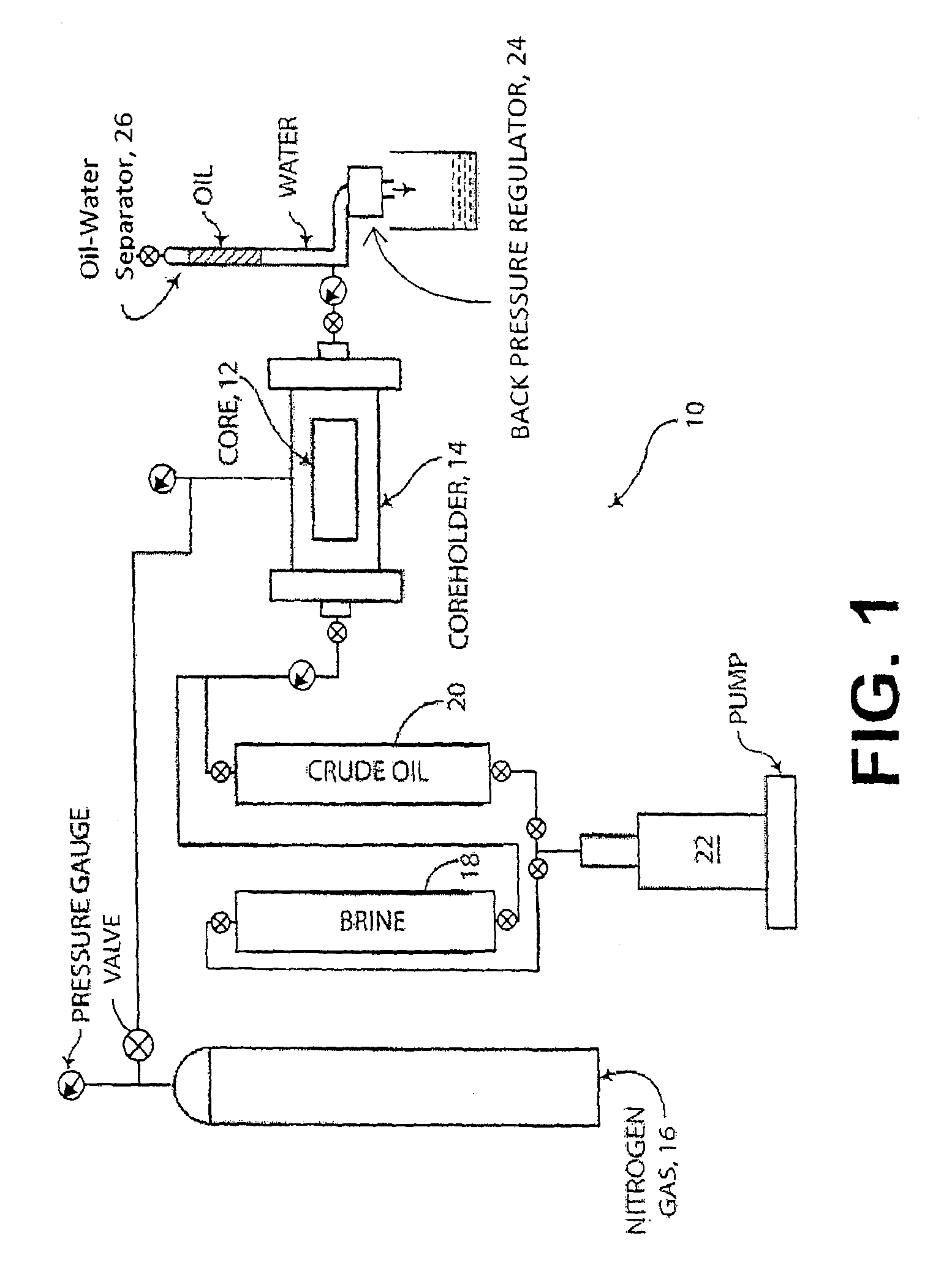
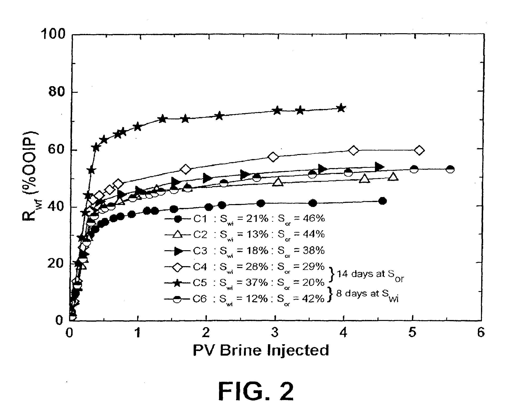
  • Single-well diagnostics and increased oil recovery by oil injection and sequential waterflooding
  • Single-well diagnostics and increased oil recovery by oil injection and sequential waterflooding
  • Single-well diagnostics and increased oil recovery by oil injection and sequential waterflooding

Examples


Embodiment Construction

[0023]Briefly, the present invention includes a method for improving oil recovery from reservoirs by reducing the residual oil saturation of oil trapped in an oil reservoir such that overall recovery is improved. The invention may be adapted to wells where the local oil saturation has different levels of mobility. In accordance with embodiments of the present invention, oil recovery may be improved by recharging the region around a previously waterflooded production or injection well with oil followed by recovery of the injected oil plus oil that was present in the reservoir after the initial waterflooding and prior to the oil injection. Oil injection may be followed by injection of water which pushes the injected oil away from the well bore to form a growing oil bank since, as a result of the second waterflooding, the residual oil in the volume swept by the oil bank is lower than the residual oil ahead of the oil bank. If the well is placed in production, a third waterflooding occu...


PUM


Abstract

A method for residual oil recovery from oil reservoirs, and diagnostic tests for determining its efficiency using a single well are described. The method includes injecting oil into a well in a reservoir that has been previously waterflooded or an oil reservoir or zone of an oil reservoir which contains immobile oil at the time of discovery, and extracting the oil by waterflooding the charged zones by placing the injection well in production. The target zone from which oil is recovered may be increased by following injection of oil with injection of water to push an oil bank which grows in volume as a function of distance of propagation, because of the effect of waterflooding on residual oil. The well may then be placed in production and the oil bank volume will continue to increase in volume as it returns to the well, again because of the waterflooding effect. The oil bank is then produced at the surface. The double-sweep waterflooding process using a single well can be repeated by again charging with oil followed by waterflooding. Sequential injection of oil and water to generate more than one oil bank may also be used to increase oil recovery by multiple sequential waterfloods. Combinations of oil injection and sequential waterflooding also have application to reservoir diagnostics.

Description

RELATED CASES[0001]The present patent application claims the benefit of U.S. Provisional Patent Application No. 61 / 226,709 for “Single-Well Diagnostics and Increased Oil Recovery by Oil Injection and Sequential Waterflooding” by Norman R. Morrow et al., which was filed on Jul. 18, 2009, the disclosure and teachings of which are hereby incorporated by reference herein.FIELD OF THE INVENTION[0002]The present invention relates generally to enhancing oil recovery from underground reservoirs and, more particularly, to increasing oil recovery from previously waterflooded reservoirs, or from an oil reservoir or zone of an oil reservoir which contains immobile oil at the time of discovery, by single-well recharging of reservoir pore spaces with oil followed by re-waterflooding and oil recovery.BACKGROUND OF THE INVENTION[0003]About one-half of oil recovery worldwide is produced by waterflooding. Typically, more than one-half of the original oil in place remains in the reservoir after waterf...

Claims


Application Information

Patent Timeline
IPC IPC(8): E21B43/16E21B47/00E21B43/25
CPCC09K8/58E21B43/25E21B43/16
Inventor MORROW, NORMAN R.XIE, SHEENA XINALOAHARDJO, NINA
Owner UNIVERSITY OF WYOMING
Learn More