Wire connecting method and wiring harness

a wire connection and wire harness technology, applied in the direction of electrically conductive connections, cable junctions, cable terminations, etc., can solve the problems of small pressure-bonded range of core wires b>101/b>, and reduce costs

Inactive Publication Date: 2013-01-31
YAZAKI CORP
View PDF6 Cites 22 Cited by
  • Summary
  • Abstract
  • Description
  • Claims
  • Application Information

AI Technical Summary

Benefits of technology

[0030]As explained above, according to the inventions claimed in claims 1 to 4, the core wire size of the second covered wire is reduced by the ultrasonic processing, and the core wire of the second covered wire is crimped or press-connected to the terminal. Therefore, the core wire of the second covered wire having the core wire size lar

Problems solved by technology

However, in the wire barrel 201, there is a problem that a range of a size of the core wire 101 allowed to be pressure-bonded is small.
In an

Method used


Image

  • Wire connecting method and wiring harness
  • Wire connecting method and wiring harness
  • Wire connecting method and wiring harness

Examples


Embodiment Construction

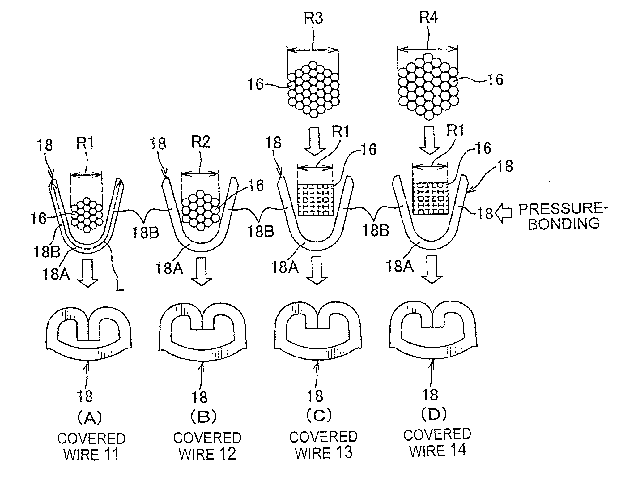
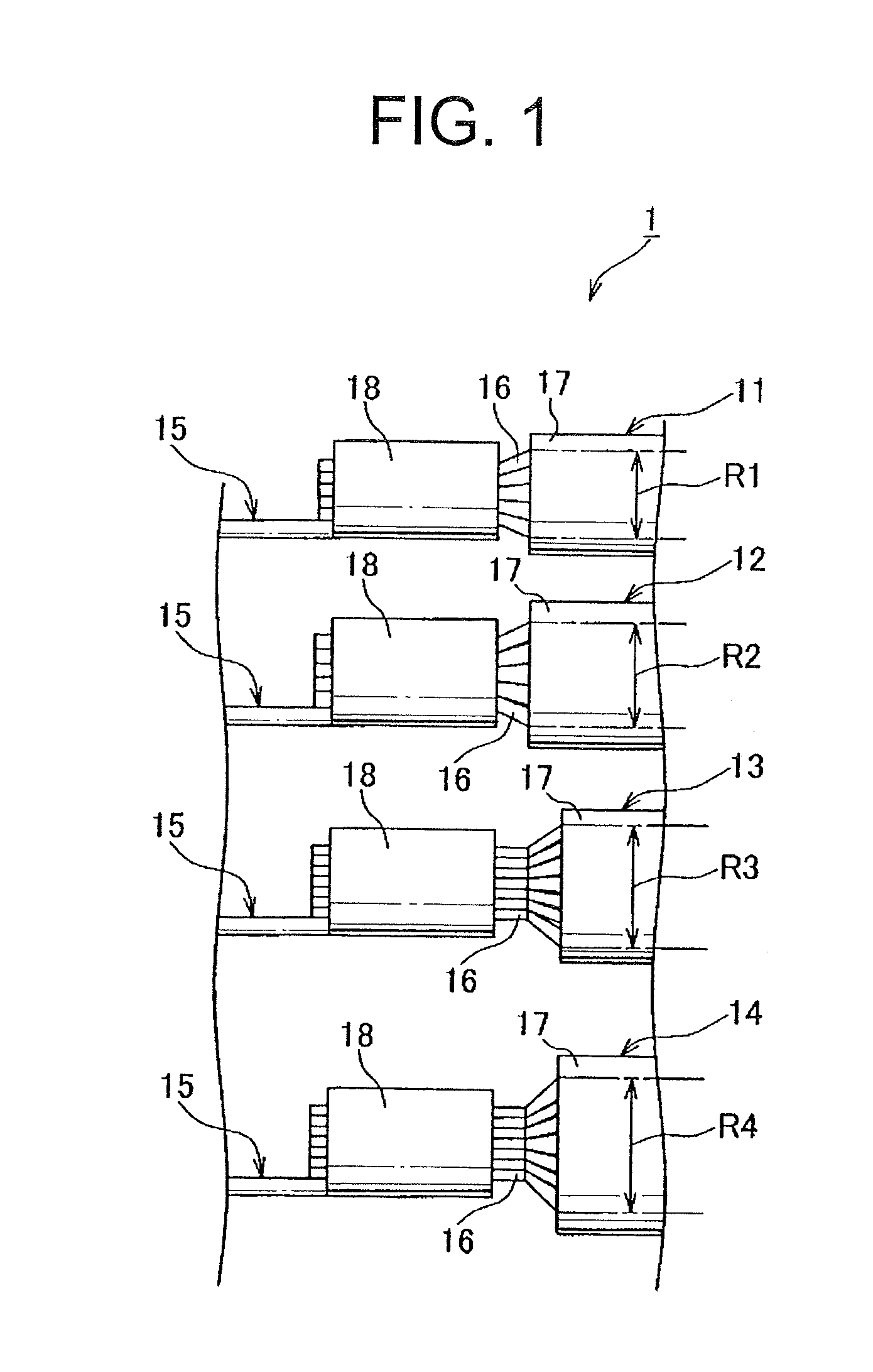
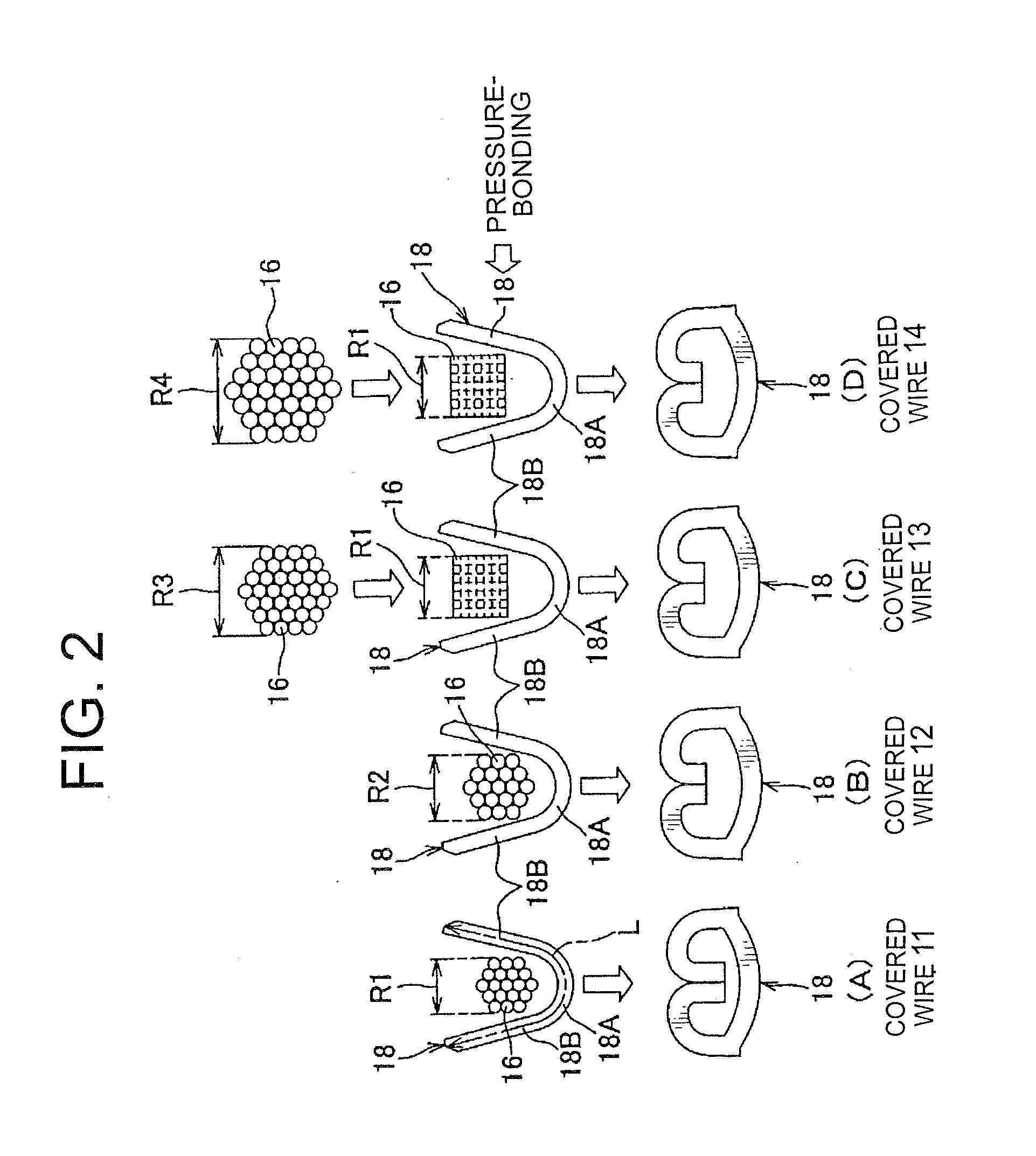
[0047]Hereinafter, a wire connecting method and a wiring harness according to the present invention will be explained with reference to FIGS. 1 to 3. As shown in FIG. 1, a wiring harness 1 includes: a plurality of types of covered wires 11 to 14 having different core wire diameters (core wire sizes) R1 to R4; and a plurality of terminals 15 connected to these covered wires 11 to 14. Each of the covered wires 11 to 14 includes: a core wire 16 made of braided conductive element wires; and an insulating cover 17 covering the core wire 16. Incidentally, the core wire diameters R1 to R4 of the covered wires 11 to 14 are provided bigger in order of the covered wire 11, the covered wire 12, the covered wire 13, and the covered wire 14 (namely, R1234).

[0048]The terminals 15 are formed in the same shape and in the same size. The terminal 15 is provided with a not-shown electric contact portion attached to a metallic panel of a vehicle body, or connected to a mating terminal, and a wire barre...


PUM

PropertyMeasurementUnit
Digital informationaaaaaaaaaa
Pressureaaaaaaaaaa
Diameteraaaaaaaaaa

Abstract

[Technical Problem]An object of the present invention is to provide a wire connecting method and a wiring harness allowed to reduce the number of types of terminals for reducing cost by increasing the number of core wire sizes able to be crimped or press-connected with respect to one terminal.
[Solution to Problem]Regarding covered wires 13, 14 of which core wire diameter is larger than the core wire diameter allowed to be crimped with a wire barrel 18, an ultrasonic processing in which while pressure is applied to a core wire 16, ultrasonic energy is applied to the core wire 16 is performed. Thereby, the core wire diameter is reduced to be allowed to be crimped to the wire barrel 18, and the core wire 16 of the covered wire 13, 14 is crimped or press-connected between a pair of crimping pieces 18B of the terminal 15. Regarding covered wires 11, 12 of which core wire diameter is allowed to be crimped to the wire barrel 18, the ultrasonic processing is not performed, and the core wire 16 of the covered wire 13, 14 is directly crimped between the pair of crimping pieces 18B of the terminal 15.

Description

TECHNICAL FIELD [0001]This invention relates to a wire connecting method and a wiring harness, in particular, to a wire connecting method for connecting terminals with a plurality of types of covered wire having core wire sizes different from each other, and to a wiring harness having a plurality of types of covered wire having core wire sizes different from each other, and terminals connected to the covered wires.BACK GROUND ART [0002]Various electronic devices are mounted on a vehicle as a moving body. A wiring harness is routed in the vehicle for supplying electric power from a power source such as a battery and a control signal from a controller to the electronic devices. The wiring harness includes: a plurality of covered wires; and terminals connected to ends of the covered wires.[0003]As an example of a connecting method for connecting terminals with the ends of the covered wires, for example, a method using pressure bonding shown in FIG. 5 is known (for example, PLT1, PLT2)....

Claims


Application Information

Patent Timeline
IPC IPC(8): H02G15/02H01R43/00
CPCH01R4/184H01R43/0207Y10T29/49194H01R4/20H01R4/2495H01R43/048
Inventor TAKAYAMA, TSUTOMUKOBAYASHI, HIROSHIMURAMATSU, SAORIKAI, SHINYANAKAJIMA, TAKAHITO
Owner YAZAKI CORP
Why Eureka
Try Eureka