Surgical Fastener Applying Apparatus

a technology of surgical stapling and applying apparatus, which is applied in the field of surgical stapling instruments, can solve the problems of affecting the healing of patients, and limiting the blade of the knife, and causing discomfort or pain to patients

Inactive Publication Date: 2013-01-31
TYCO HEALTHCARE GRP LP
View PDF16 Cites 74 Cited by
  • Summary
  • Abstract
  • Description
  • Claims
  • Application Information

AI Technical Summary

Problems solved by technology

However, because the knife blade is limited by geometry, i.e., a diameter of the knife blade is smaller than a diameter of the annular array of formed staples, the lumen created through the joined tissue is, typically, small in relation to the anvil member.
As can be appreciated, trying to remove the anvil through the relatively small lumen may prove to be arduous task.
Moreover, the relatively small lumen or “stricture” may function as collection points for diviticular, which, in turn, may cause discomfort or pain to a patient or, worse, develop into a more serious ailment, e.g., diverticulitis, colon cancer, etc.

Method used


Image

  • Surgical Fastener Applying Apparatus
  • Surgical Fastener Applying Apparatus
  • Surgical Fastener Applying Apparatus

Examples


Embodiment Construction

[0024]Detailed embodiments of the present disclosure are disclosed herein; however, the disclosed embodiments are merely examples of the disclosure, which may be embodied in various forms. Therefore, specific structural and functional details disclosed herein are not to be interpreted as limiting, but merely as a basis for the claims and as a representative basis for teaching one skilled in the art to variously employ the present disclosure in virtually any appropriately detailed structure.

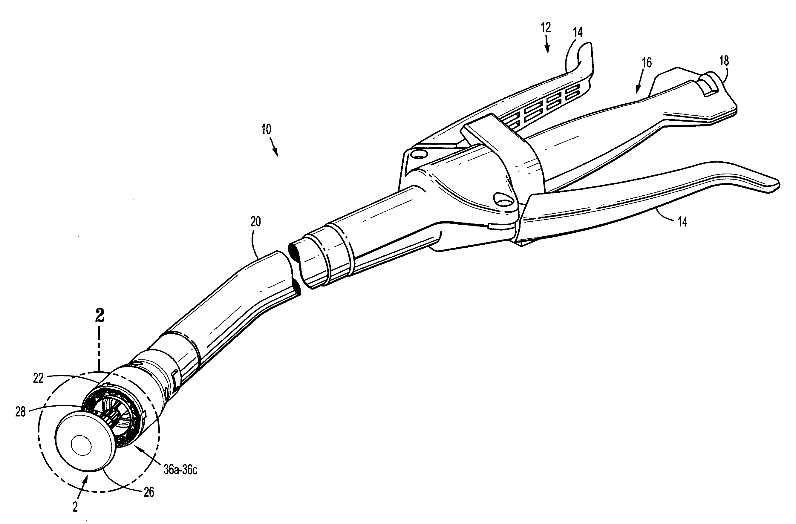
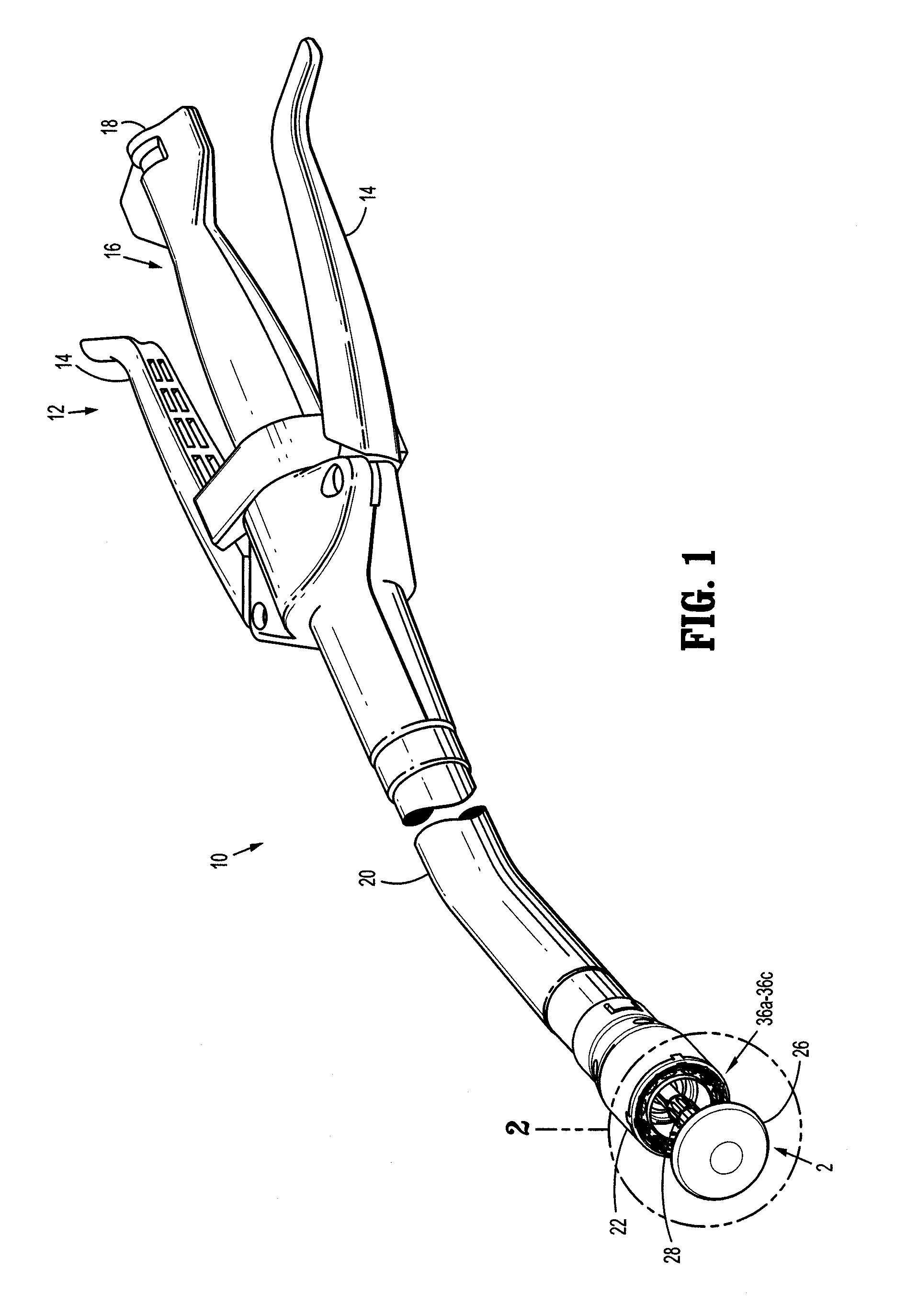
[0025]In the drawings and in the descriptions that follow, the term “proximal,” as is traditional, will refer to the end of a surgical instrument that is closer to the user, while the term “distal” will refer to the end of the surgical instrument that is farther from the user.

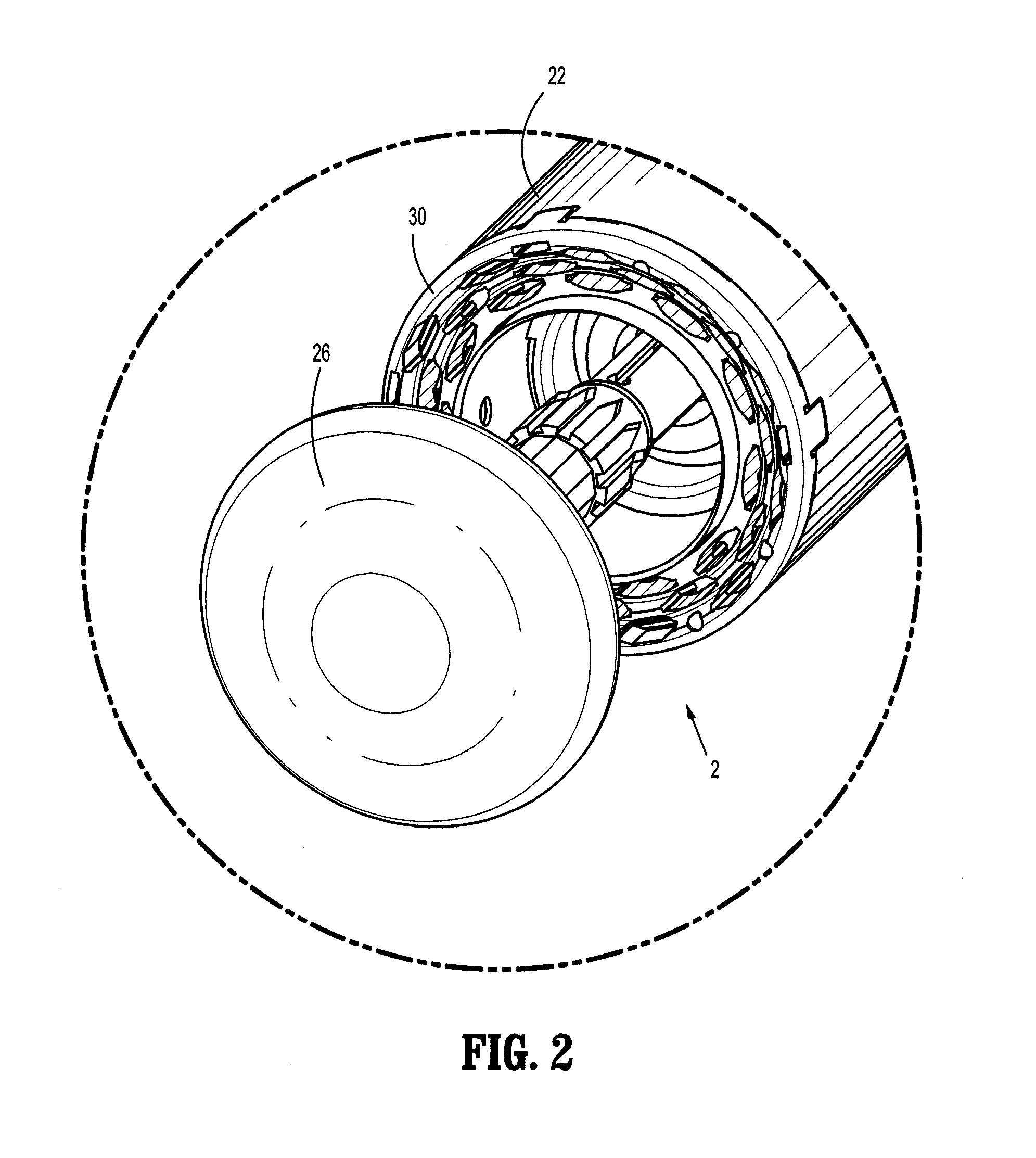
[0026]Referring now in specific detail to the drawings, in which like reference numerals identify similar or identical elements throughout the several views, FIG. 1 shows a staple fastening assembly 2 (assembly 2) adapted for...


PUM

PropertyMeasurementUnit
lengthaaaaaaaaaa
sizeaaaaaaaaaa
diameteraaaaaaaaaa

Abstract

A surgical stapler is provided. The surgical stapler includes a tubular body portion. A cartridge assembly (cartridge) is disposed at a distal end of the tubular body portion and defines a longitudinal axis therethrough. The cartridge includes a distal face having a stepped configuration defined by outer and inner steps arranged in descending order from the outer step to the inner step. An anvil member is disposed at the distal end of the tubular body portion and is positioned opposite the cartridge. The anvil member includes a proximal face having a stepped configuration defined by outer and inner steps arranged in descending order from the outer step to the inner step. The steps defined in the proximal face of the anvil member having a respective annular array of staple forming buckets disposed thereon to clinch the staples in tissue upon expulsion of the staples from the cartridge.

Description

BACKGROUND[0001]1. Technical Field[0002]The present disclosure relates to surgical stapling instruments for applying surgical fasteners or staples to body tissue and, more particularly to surgical stapling instruments for applying an annular array of surgical staples or fasteners.[0003]2. Description of Related Art[0004]Surgical stapling devices for applying an annular array of staples or fasteners to tissue are well known in the art. For example, such surgical stapling devices have particular utility in performing small bowl resection with end-to-end anastomosis. These devices, typically, include a staple pusher assembly or member and an anvil assembly or member at the distal end of the surgical stapling device. One or more annular or circular arrays of fasteners, such as, for example, staples, is operably housed in the cartridge assembly. The anvil member includes one or more corresponding annular arrays of staple forming bucket members that clinch or form (e.g., in a “B” staple f...

Claims


Application Information

Patent Timeline
Patent Type & Authority Applications(United States)
IPC IPC(8): A61B17/068
CPCA61B2017/07214A61B17/1155
Inventor MOZDZIERZ, PATRICKPENNA, CHRISTOPHER
Owner TYCO HEALTHCARE GRP LP
Why Eureka
Try Eureka