Segmented stator for an axial field device

a technology of axial field and axial field, which is applied in the direction of dynamo-electric components, dynamo-electric machines, magnetic circuit shapes/forms/construction, etc., can solve the problems of limited size of machines that may be produced with a one-piece printed circuit board (pcb) stator, and higher cost due to more labor and higher material costs

Active Publication Date: 2011-11-10
BWP GRP
View PDF0 Cites 75 Cited by
  • Summary
  • Abstract
  • Description
  • Claims
  • Application Information

AI Technical Summary

Benefits of technology

[0003]The present invention provides an axial rotary energy device which is arranged in a multi-phase electric current configuration. The device includes a rotor having a plurality of permanent magnet poles secured thereto and further includes a segmented stator assembly having a plurality of segments arranged in an annular array. Each stator segment is constructed by stacking a plurality of printed circuit board power conductor layers together with a plurality of much larger diameter machine than is possible with single piece PCB stator designs. Further, the segments may be produced in high volume manufacturing facilities that provide the best cost.

Problems solved by technology

The size of machines that may be produced with a one-piece printed circuit board (PCB) stator is limited by the capability of the processing equipment found in a PCB manufacturing facility.
Certain lower volume facilities routinely process larger PCB panel sizes than the high volume manufacturers but there is a higher cost due to more labor and higher material costs.

Method used


Image

  • Segmented stator for an axial field device
  • Segmented stator for an axial field device
  • Segmented stator for an axial field device

Examples


Embodiment Construction

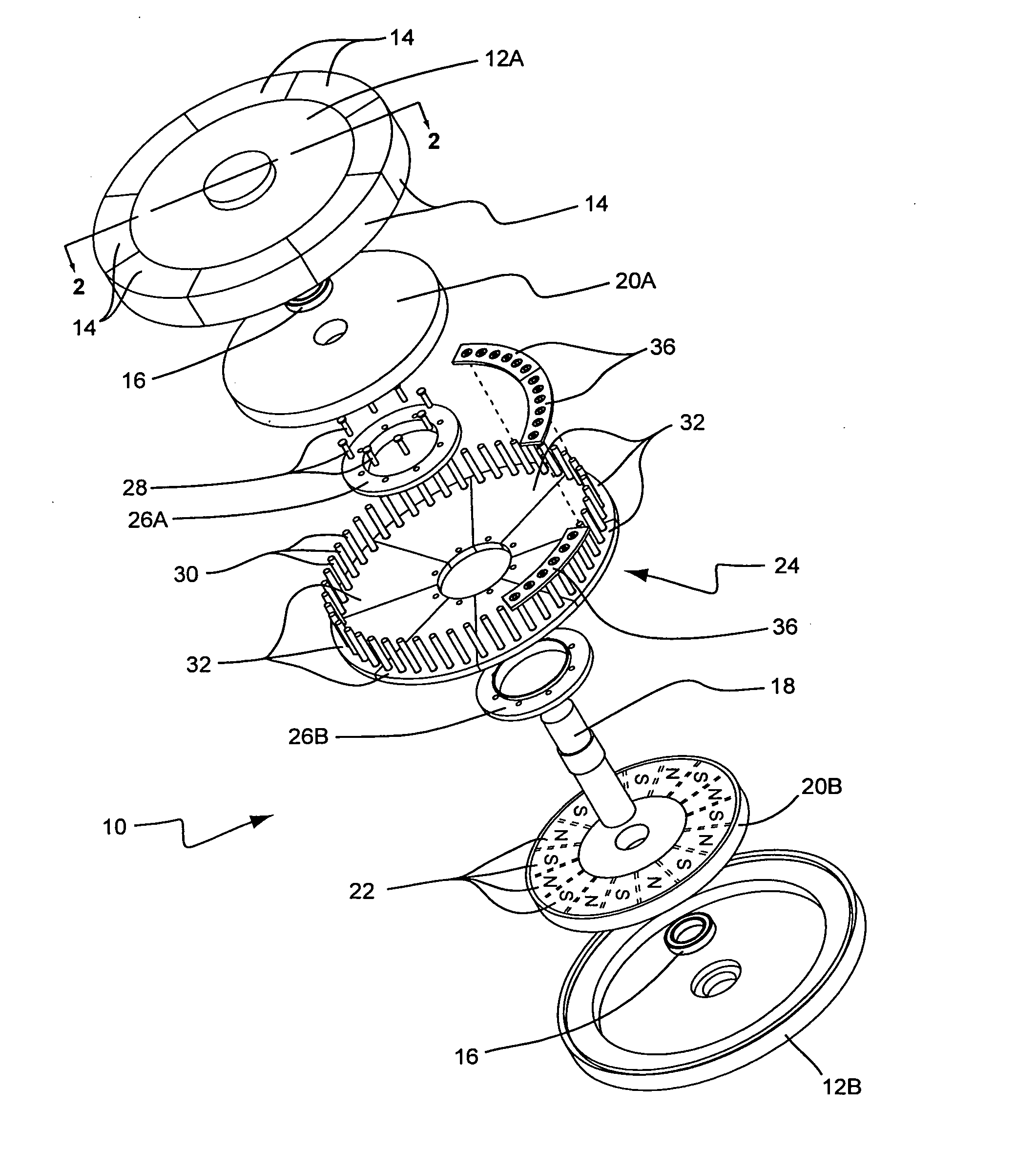
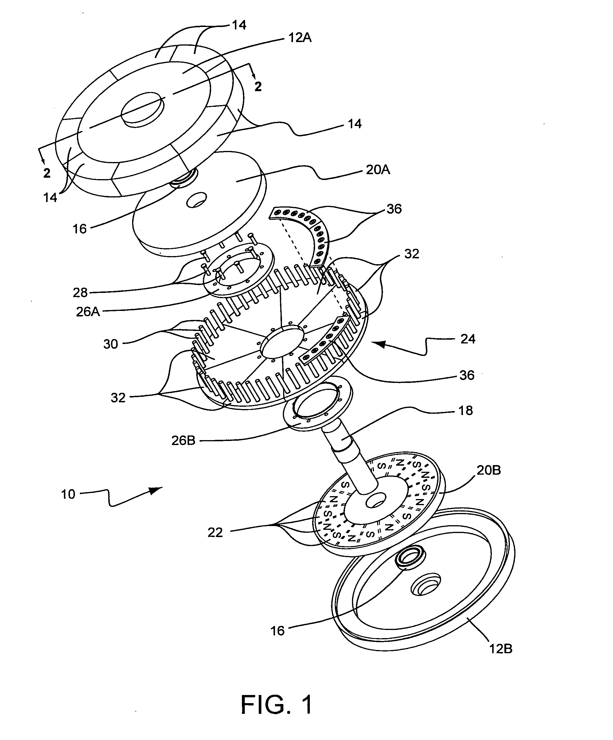
[0026]An axial gap device 10 according to the present invention is shown in FIG. 1 with a housing 12A having a number of terminal covers 14, a pair of bearings 16, a drive shaft 18, a pair of rotors 20A and 20B each having an annular array of permanent magnets 22 that alternate polarity around the array, another housing 12B, and a segmented stator assembly 24. The segmented stator assembly 24 is comprised of a pair of clamp rings 26A and 26B, a number of fasteners such as bolts 28, a plurality of terminal lugs 30, and a plurality of stator segments 32. The stator segments 32 are comprised of multiple layer printed circuit boards that are shaped to fit together to form an annular array of stator segments 32. The multiple layers of conductive material in each stator segment 32 provide a number of turns for each electrical phase of the axial gap device 10.

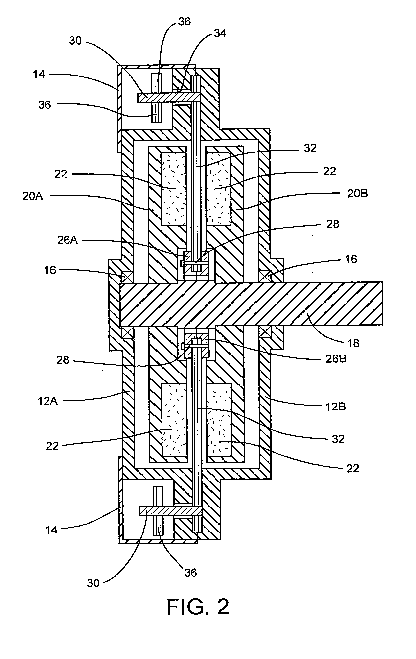
[0027]FIG. 2 illustrates how the clamp rings 26A and 26B and bolts 28 fasten onto either side of the inward edge of the stator segme...


PUM


Abstract

An axial rotary energy device including a segmented stator assembly having a plurality of segments arranged in an annular array. Each stator segment is constructed by stacking a plurality of PCB power conductor layers and a plurality of PCB series layers. Each layer having radial conductors extending from an inner via to an outer via. The vias electrically connect selected radial conductors of the series conductor layer and power conductor layer. Each power conductor layer includes a pair of positive and negative terminal vias for one phase of the electric current connected to selected outer vias. A daughter PCB layer electrically connects two adjacent segments together by having a first portion electrically connected to a negative terminal via located in one segment and a second portion electrically connected to a positive terminal via located in an adjacent segment together with a current conductor electrically connecting the two terminal vias together.

Description

FIELD OF THE INVENTION[0001]The present invention relates to an improved stator for an axial field rotary energy device operating as a motor or a generator as described in U.S. Pat. No. 7,109,625 to Jore et al.BACKGROUND OF THE INVENTION[0002]The size of machines that may be produced with a one-piece printed circuit board (PCB) stator is limited by the capability of the processing equipment found in a PCB manufacturing facility. High volume facilities have a maximum size PCB panel that can be processed on automated equipment. Certain lower volume facilities routinely process larger PCB panel sizes than the high volume manufacturers but there is a higher cost due to more labor and higher material costs. In order to cost effectively produce large axial field rotary machines that incorporate a PCB stator, a segmented PCB stator is shown and described. The segments allow a much larger diameter machine than is possible with single piece PCB stator designs. Further, the segments may be pr...

Claims


Application Information

Patent Timeline
Patent Type & Authority Applications(United States)
IPC IPC(8): H02K21/24
CPCH02K1/12H02K3/26H02K2211/03H02K21/24H02K2203/03H02K3/47
Inventor JORE, MATTHEW B.DUFORD, JAMES DAVIDKVAM, MICHAELJORE, LINCOLN M.SAMSEL, DAVIDJORE, JAMES D.
Owner BWP GRP
Why Eureka
Try Eureka