Fixed pattern detection apparatus

a technology of fixed pattern and detection apparatus, which is applied in the field of correlation, can solve the problems of difficult to reduce the power consumption and production cost of mobile terminal equipment, the ratio of signal to noise at the front end of the receiver is extremely low, and achieves the effect of reducing the time consumed in detection

Inactive Publication Date: 2005-04-19
NEC CORP
View PDF8 Cites 68 Cited by
  • Summary
  • Abstract
  • Description
  • Claims
  • Application Information

AI Technical Summary

Benefits of technology

[0021]It is therefore a principal object according to an aspect of the present invention to provide a fixed pattern detection device in the CDMA communication system in which, in detecting a fixed pattern from...

Problems solved by technology

Thus, the S/N (signal to noise) ratio at the front end of the receiver is extremely low.
The result is that the power consumption is increased to r...

Method used


Image

  • Fixed pattern detection apparatus
  • Fixed pattern detection apparatus
  • Fixed pattern detection apparatus

Examples


first embodiment

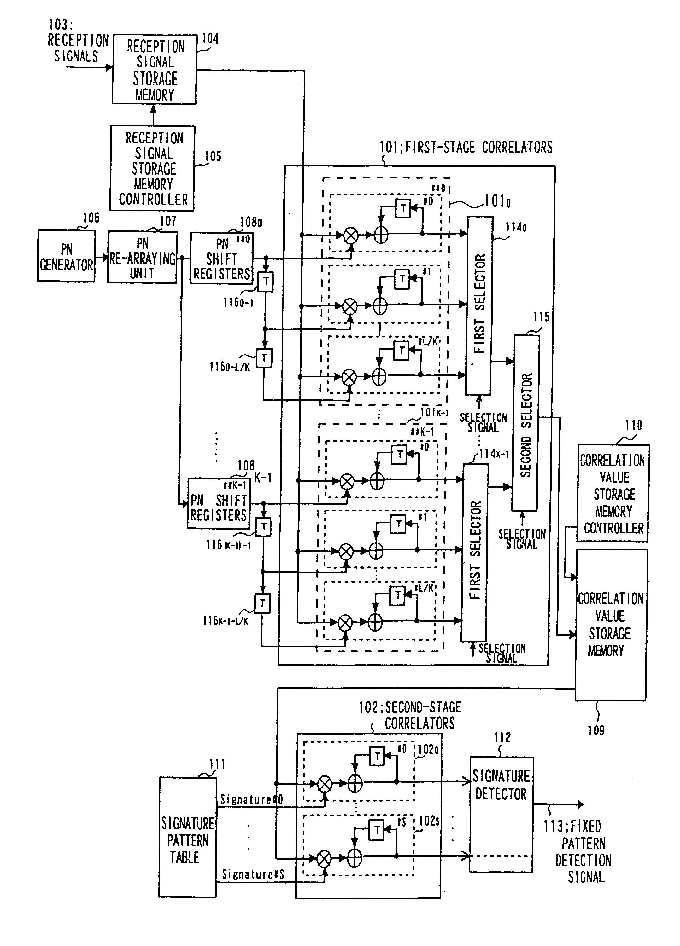
[0104]If, in the present invention, the first-stage correlators 101 are provided with K correlator blocks 1010 to 101K−1, and the first-stage correlators 101 calculates the correlation values for M+L / K chips, the number of times of readout from the received signal storage memory 104 is M+L / K, so that, for the entire K stages, the number of times of readout operations is equal to M+L / K so that, for the entire K operations, it is (M+L / K)×K=N+L.

[0105]By constructing the respective correlator blocks 1010 to 101K−1 by L / K+1 correlators, and by calculating, in the respective correlator blocks, the correlation values of the PN sequences, delayed from correlator to correlator in synchronism with the received signal readout period, with the read-out received signals, by L / K+1 correlators, the number of times of readout operations from the received signal storage memory 104 is N+L.

[0106]If, in a Preferred embodiment of the present invention, there exist Plural signature patterns, plural sorts...

second embodiment

[0109]For example, if the indefinite time width L=512, the length K of the signature pattern is K=16, each correlator block includes L / K+1=33 correlators, so that 16×33=528 correlators are required for the 16 correlator blocks in their entirety. However, in the present invention, if n=2, as an example, each of 16 correlator blocks is made up of L / K+1=17 correlators, such that, for the 16 correlator blocks, a sum total of 16×17=272 correlators are required for 16 correlator blocks, such that the circuit scale is substantially halved as compared to the previous embodiment, insofar as the correlators are concerned.

[0110]FIG. 10 shows, by an overview, the readout of the first received signal sequence (C0, CK, C2K, . . . ) and input signal pairs to the multiplier of the correlation values in the correlator of each correlator block. In FIG. 10 the abscissa denotes an operating Period for M+L / (n×K) periods. In the following, the points of difference from FIG. 5 are explained.

[0111]Referrin...


PUM


Abstract

A fixed pattern detection device in which the device is fed as a received signal with a pattern of a length of N chips. The received signal is obtained by dividing and re-arraying each of K (integer) symbols in terms of a chip period as a unit, each symbol being spread with the spread code (PN) at a rate of M (integer) chips per symbol, and on repeatedly inserting into the re-arrayed symbols a signature pattern of a length K having one chip period as a unit, by M times, where N=K×M. The device includes first-stage correlators taking correlation between M received signals and M spread code sequences obtained on decimating a spread code sequence of a length N, and a second stage correlators taking correlation between the correlation values associated with K signatures output by the first-stage correlators and a pre-defined signature pattern.

Description

FIELD OF THE INVENTION[0001]This invention relates to a correlator and, more particularly, to a correlator usable with advantage in detecting a fixed pattern in a reception device of the CDMA communication system.BACKGROUND OF THE INVENTION[0002]The spread spectrum communication system is such a one in which a transmitter modulates a transmission signal and spectrum-spreads the modulated transmission signal using a spread code (pseudorandom noise, herein abbreviated as “PN”), to transmit the spectrum-spread signal, and in which a receiver upon receiving and demodulating the spectrum-spread signal, transmitted from the transmitter, inverse-spreads (despreads) the received spectrum-spread signal, using the same PN sequence as that used for spreading in the transmitter. It is only when a PN sequence contained in the received signal coincides with that generated on the receiver side that correct demodulation is achieved.[0003]Recently, the CDMA (Code Division Multiple Access) communicat...

Claims


Application Information

Patent Timeline
IPC IPC(8): H04B1/707H04B1/709H04L7/00
CPCH04B1/707H04B1/7095H04B1/709H04B2201/70701
Inventor TANAKA, HIROKI
Owner NEC CORP
Why Eureka
Try Eureka