Integrated solid oxide fuel cell and fuel processor

a solid oxide fuel cell and fuel processor technology, applied in the field of solid oxide fuel cells and the fuel processing, can solve the problems of limiting the practicality of its use, low activation voltage loss of sofc, and expensive fabrication methods

Active Publication Date: 2008-02-14
MODINE MFG CO
View PDF99 Cites 80 Cited by
  • Summary
  • Abstract
  • Description
  • Claims
  • Application Information

AI Technical Summary

Problems solved by technology

The rate at which a fuel cell's electrochemical reactions proceed increases with increasing temperature, resulting in lower activation voltage losses for the SOFC.
However, there are several known disadvantages to the tubular design which severely limit the practicality of its use in the area of 25 kW-100 kW distributed stationary power generation.
For example, producing the tubes can require expensive fabrication methods, resulting in achievable costs per kW which are not competitive with currently available alternatives.
As another example, the electrical interconnects between tubes can suffer from large ohmic losses, resulting in low volumetric power densities.
These disadvantages to the tubular designs have led to the development of planar SOFC designs.
However, there are still challenges to implementing the planar SOFC for stationary power generation in the range of 25 kW-100 kW.
The practical size of such cells is currently limited to a maximum footprint of approximately 10×10 cm by issues such as the thermal stresses within the plane of the cell during operation and the difficulties involved in fabricating very thin components.
Implementing large numbers of such cells presents several difficulties.
A planar SOFC design requires high-temperature gas-tight seals around the edges of the cells, which typically requires large compressive loads on the stack.
These issues and others have made it difficult for planar SOFC manufacturers to progress to fuel cell systems larger than about 5 kWe.

Method used


Image

  • Integrated solid oxide fuel cell and fuel processor
  • Integrated solid oxide fuel cell and fuel processor
  • Integrated solid oxide fuel cell and fuel processor

Examples


Embodiment Construction

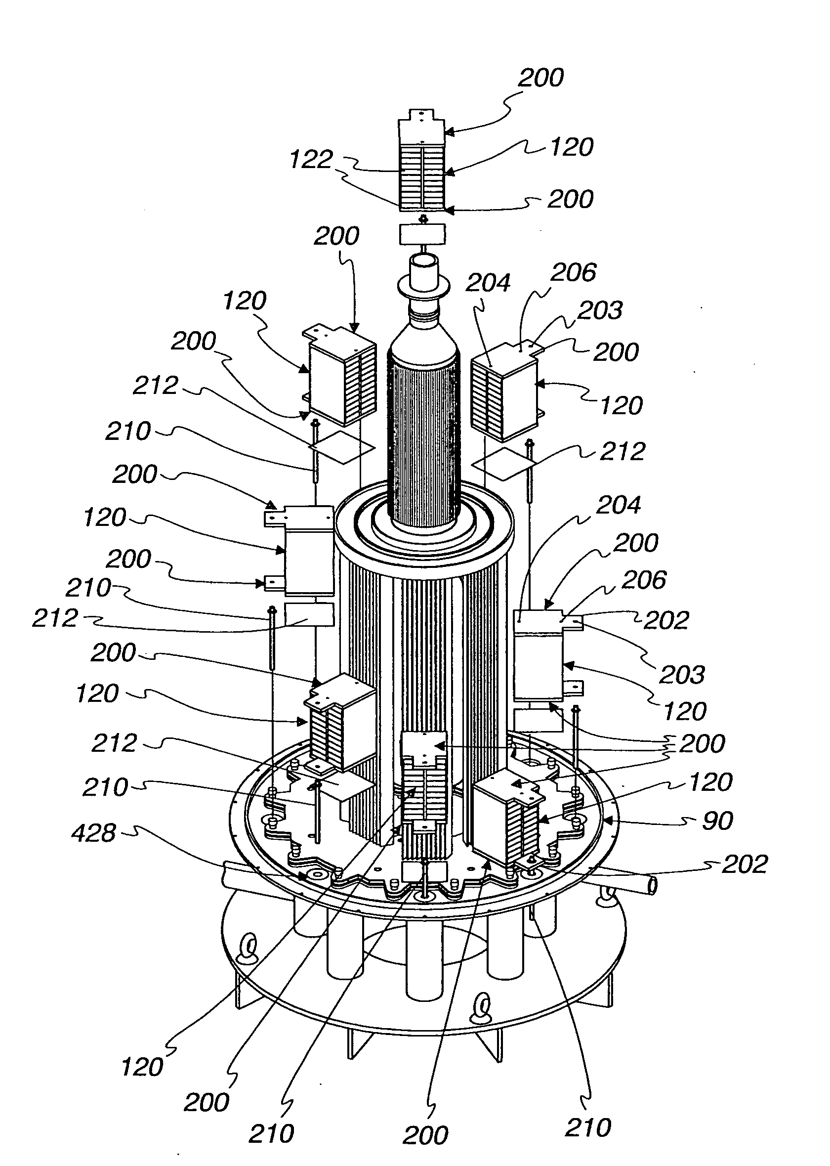
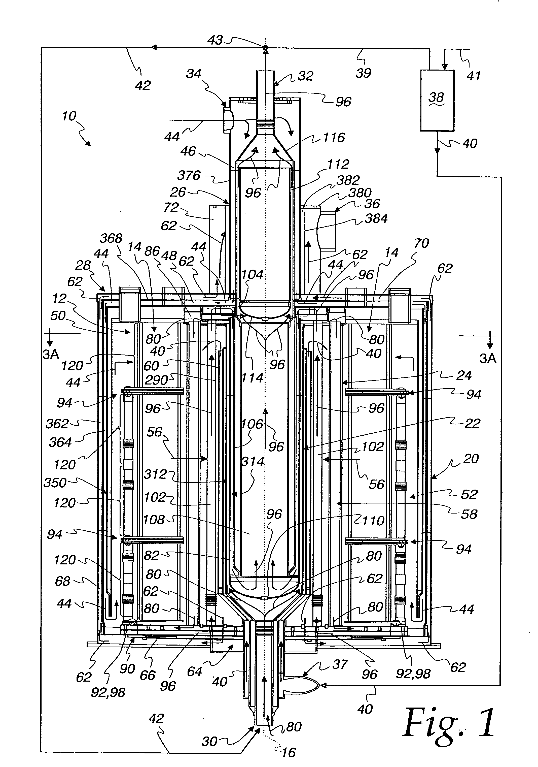
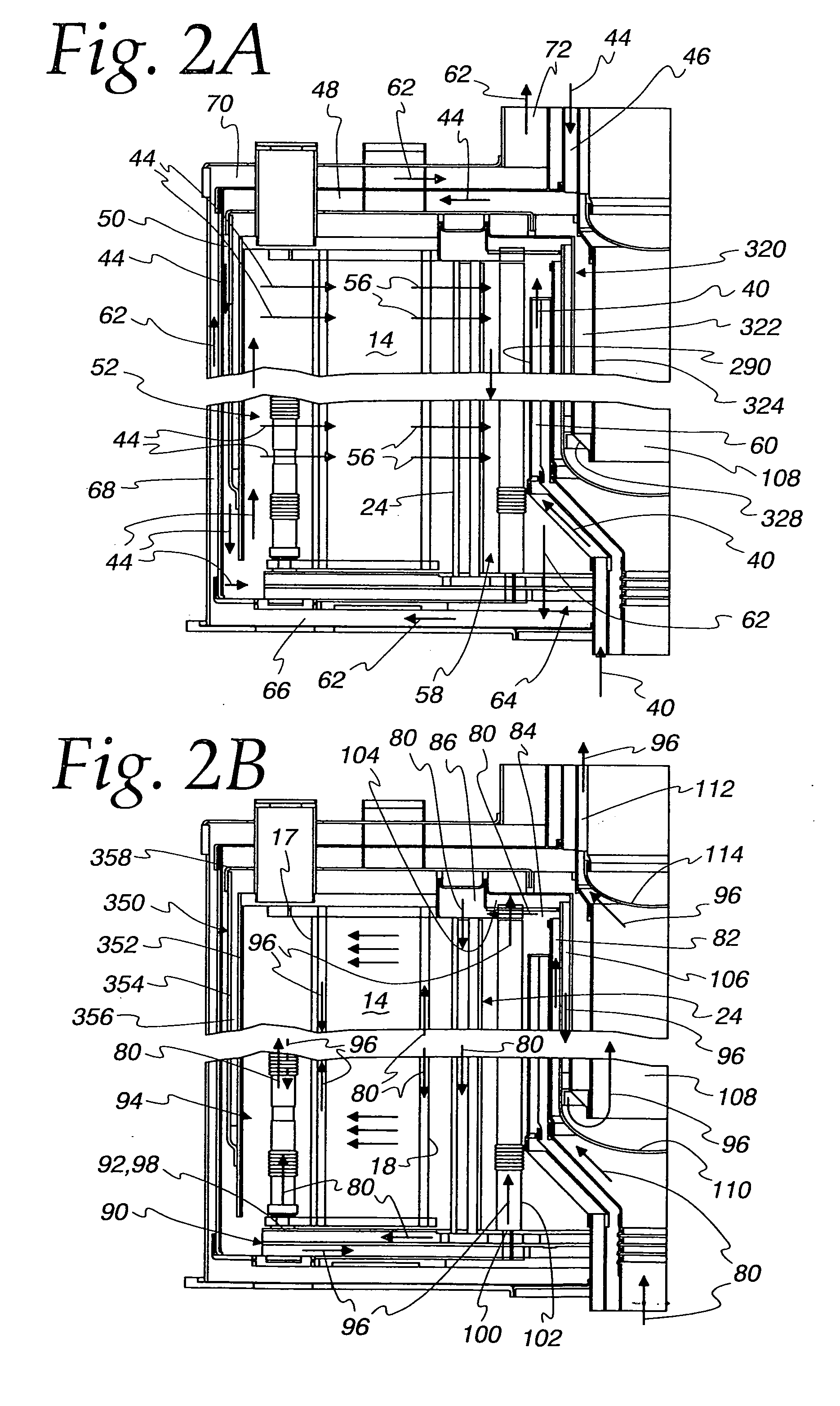
[0055]With reference to FIGS. 1, 2A, 2B and 3A, an integrated fuel cell unit 10 is shown in form of an integrated solid oxide fuel cell (“SOFC”) / fuel processor 10 having a generally cylindrical construction. The unit 10 includes an annular array 12 of eight (8) fuel cell stacks 14 surrounding a central axis 16, with each of the fuel cell stacks 14 having a stacking direction extended parallel to the central axis 16, with each of the stacks having a face 17 that faces radially outward and a face 18 that faces radially inward. As best seen in FIG. 3A the fuel cell stacks 14 are spaced angularly from each other and arranged to form a ring-shaped structure about the axis 16. Because there are eight of the fuel cell stacks 14, the annular array 12 could also be characterized as forming an octagon-shaped structure about the axis 16. While eight of the fuel cell stacks 14 have been shown, it should be understood that the invention contemplates an annular array 12 that may include more than...


PUM

PropertyMeasurementUnit
poweraaaaaaaaaa
sizeaaaaaaaaaa
pressureaaaaaaaaaa

Abstract

An integrated fuel cell unit (10) includes an annular array (12) of fuel cell stacks (14), an annular cathode recuperator (20), an annular anode recuperator (22), a reformer (24), and an anode exhaust cooler (26), all integrated within a common housing structure (28).

Description

FIELD OF THE INVENTION[0001]This invention relates to solid oxide fuel cells and the fuel processing associated therewith.BACKGROUND OF THE INVENTION[0002]Solid oxide fuel cells (“SOFC's”) and associated fuel processors are known. SOFC's are solid-state devices which use an oxygen ion conducting ceramic electrolyte to produce electrical current by transferring oxygen ions from an oxidizing gas stream at the cathode of the fuel cell to a reducing gas stream at the anode of the fuel cell. This type of fuel cell is seen as especially promising in the area of distributed stationary power generation. SOFC's require an operating temperature range which is the highest of any fuel cell technology, giving it several advantages over other types of fuel cells for these types of applications. The rate at which a fuel cell's electrochemical reactions proceed increases with increasing temperature, resulting in lower activation voltage losses for the SOFC. The SOFC's high operating temperature can...

Claims


Application Information

Patent Timeline
Patent Type & Authority Applications(United States)
IPC IPC(8): H01M8/24H01M8/04
CPCH01M8/2475H01M8/248H01M8/2485H01M8/249Y02E60/521Y02E60/525H01M8/247H01M8/04007H01M8/0625H01M8/0631H01M8/12H01M8/2425H01M8/0258Y02E60/50H01M8/2483H01M8/0267H01M8/2432H01M8/2457H01M8/0263
Inventor VALENSA, JEROENREINKE, MICHAEL J.VOSS, MARK G.
Owner MODINE MFG CO
Why Eureka
Try Eureka