Eureka AIR delivers breakthrough ideas for toughest innovation challenges, trusted by R&D personnel around the world.

Optical system for a motor vehicle

Active Publication Date: 2013-01-31
VALEO VISION SA
View PDF4 Cites 14 Cited by
  • Summary
  • Abstract
  • Description
  • Claims
  • Application Information

AI Technical Summary

Benefits of technology

The invention provides a surface light source with very even distribution of light across the entire output face, which improves visibility and enhances aesthetics. The area of emission is greater than 1 cm2, and the system can be used for various road lighting functions such as a high beam, dipped beam, and fog lamp.

Problems solved by technology

However, these optical devices do not enable a homogeneous output of emission, regardless of the direction of observation, to be produced.
However, conventional OLEDs exhibit a luminance that is too low to be able to be used in an indicating or road lighting application.
These modified OLEDs exhibit several particularly disadvantageous drawbacks.
The glass sheets highly restrict the possible forms of the organic light-emitting diodes.
This therefore raises design issues.
These limitations lead to tight constraints both on the form of the system including the OLED and on the orientation of the plate which must be normal to the prioritized optical direction.
In practice, the field of application of these modified OLEDs is therefore a priori restricted.
However, the luminance of these flexible OLEDs remains relatively low and they are difficult to use, or even unusable, for passenger compartment lighting functions, and even less so for photometric functions such as indicating functions or lighting functions.

Method used


Image

  • Optical system for a motor vehicle
  • Optical system for a motor vehicle
  • Optical system for a motor vehicle

Examples


Embodiment Construction

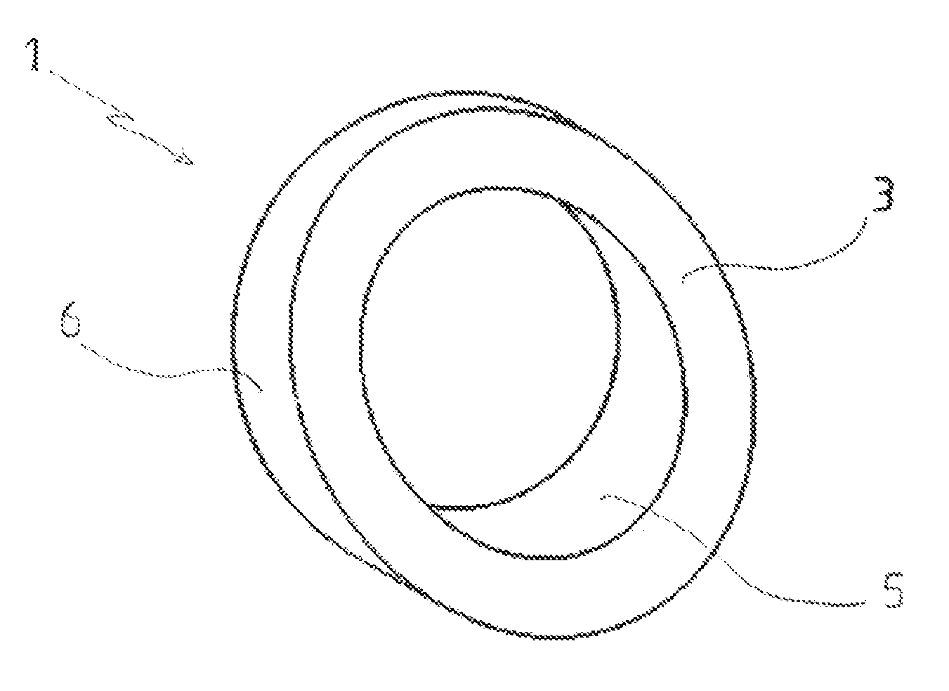
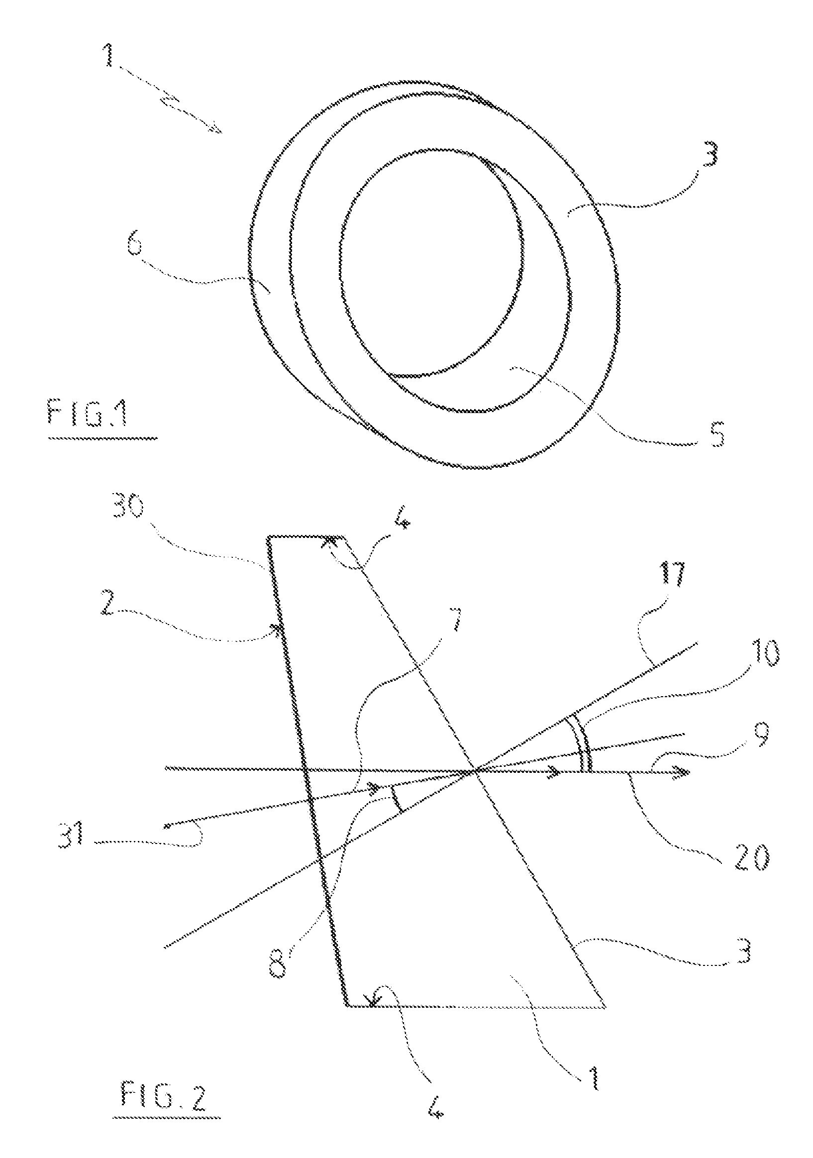
[0058]The optical system for a motor vehicle, in particular for an indicating and / or lighting device, according to the invention, is arranged to emit a light, the intensity of which is maximal in a given prioritized optical direction 20. This prioritized optical direction 20 is set when the system is being designed. In practice, this prioritized optical direction 20 is most often horizontal. When the system has a stop lamp function, a reversing lamp function or a front lighting function for the vehicle, this prioritized optical direction 20 corresponds generally to the road axis at the level of or in front of the vehicle, or to the direction of movement of the vehicle. The prioritized optical direction 20 can also be defined by a mapping system, or a steering or wheel rotation sensor, or a road bend sensor (white line sensor, etc.).

[0059]The system exhibits an outer face which is not contained in a plane that is substantially normal to the prioritized optical direction 20. This oute...


PUM


Abstract

The present invention relates to an optical system for a motor vehicle, in particular for an indicating and / or lighting device, arranged to emit a light, the intensity of which is maximal in a given prioritized optical direction (20), including:a surface light source (30) exhibiting a front wall emitting a light, the intensity of which is maximal in a principal direction of emission (31),an optical guide (1) comprising an input face (2) and an output face (3) forming at least partly an outer face of the system, the system being arranged such that the light penetrates the guide through the input face (2) and escapes through the output face (3),the optical guide (1) being conformed such that the intensity of the light at the output of the system is maximal in a prioritized optical direction (20).

Description

CROSS-REFERENCE TO RELATED APPLICATIONS[0001]This application claims priority to PCT Application PCT / EP2011 / 051736 filed Feb. 7, 2011, and also to French Application No. 1051229 filed Feb. 19, 2010, which applications are incorporated herein by reference and made a part hereof.BACKGROUND OF THE INVENTION[0002]1. Field of the Invention[0003]The present invention relates to an optical system, in particular for a motor vehicle, such as a lighting and / or indicating device having in particular a photometric function that is useful when the vehicle is moving on the road, allowing the vehicle to be seen by other vehicles or allowing the driver of the vehicle to see outside.[0004]2. Description of the Related Art[0005]Conventional visual indicating or lighting systems for motor vehicles comprise a casing containing a point source of light such as a bulb and an optical system to focus the beam in a principal direction. The outer face of the casing can exhibit varied forms and can for example...

Claims


Application Information

Patent Timeline
IPC IPC(8): F21V8/00F21V13/02
CPCF21S48/115F21S48/215F21Y2105/008F21Y2105/00F21S48/2225F21Y2115/15F21S43/145F21S43/26F21S43/315F21S43/40F21S43/235
Inventor DUBOSC, CHRISTOPHEPAUTY, ETIENNEDE LAMBERTERIE, ANTOINE
Owner VALEO VISION SA
Why Eureka
Eureka Blog
Learn More