Methods, systems and apparatus for the control of interconnection of fibre channel over ethernet devices

a technology of ethernet devices and fibre channels, applied in the field of network systems and communications networks, can solve the problems of inability to fully support the network, the protocol of the fibre channel switch fabric is complex, and the management, control and data switching areas are complicated

Inactive Publication Date: 2013-01-31
JEDA NETWORKS
View PDF2 Cites 111 Cited by
  • Summary
  • Abstract
  • Description
  • Claims
  • Application Information

AI Technical Summary

Problems solved by technology

Converging the LAN and SAN networks has created additional complexity in the management, control, and data switching areas.
Singly, the Fibre Channel switch fabric protocols are very complex and have shown to be not very interoperable between the small number of vendors who build products that support them.
Mapping the Fibre Channel switch fabric protocols over Ethernet has resulted in a dizzying amount of new standards that have inhibited the market acceptance of the Fibre Channel over Ethernet (FCoE) mapping over this new converged network.
These disadvantages include but are not limited to: the requirement for the ENode to choose a unique MAC address for each VN_Port, the requirement for the ENode to choose a unique Fibre Channel address identifier for each VN_Port, the lack of visibility into the network's supported maximum frame size or other capabilities, the lack of standardized discovery of specific ENode types such as Storage targets, the lack of the ability to automatically and dynamically create Fibre Channel zones or access control lists (ACLs) for intermediate Ethernet bridges, the lack of visibility to load balance across several paths from a source ENode to a destination ENode based on FCID's, and the increased complexity to scale to hundreds of ENodes which requires error prone manual configuration.
Due to the lack of Fibre Channel fabric control, these emerging ideas and standards target smaller networks of ENodes, which are impractical in today's Data Center.

Method used


Image

  • Methods, systems and apparatus for the control of interconnection of fibre channel over ethernet devices
  • Methods, systems and apparatus for the control of interconnection of fibre channel over ethernet devices
  • Methods, systems and apparatus for the control of interconnection of fibre channel over ethernet devices

Examples


Embodiment Construction

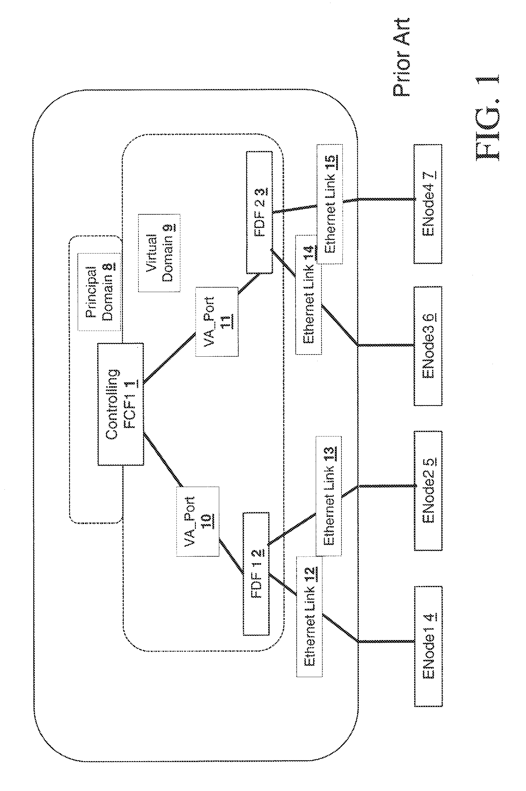
[0134]FIG. 1 shows an example of Distributed FCF composed of a Controlling FCF 1 and two FDFs 23 as described in the ANSI T11 FC-BB standards. The Controlling FCF 1 uses a Virtual Domain_ID to perform N_Port_ID allocations for ENodes 4567 connected to the FDF Set 23 of the Distributed FCF (i.e., the Virtual Domain_ID) is used as the most significant byte in all N_Port_IDs allocated to ENodes that are attached to the FDF Set). The Controlling FCF 1 uses also another Domain_ID, called Principal Domain, for its normal functions as an FCF. As a result, a Distributed FCF such as the one shown in FIG. 1 uses two Domain_IDs: one for the Principal Domain 8 and one for the Virtual Domain 9. To properly support the operations of a Virtual Domain 9, a Controlling FCF 1 shall have a Switch_Name to associate with the Virtual Domain 9, in addition to its own Switch_Name. FDFs are not able to operate properly without a Controlling FCF 1, therefore the Controlling FCF 1 is a single point of failure...


PUM


Abstract

Systems, apparatus and methods are provided for interconnection of one or more Fibre Channel over Ethernet (FCoE) devices. The system preferably comprises a virtualized or virtual server which in turn comprises a virtual machine having an FCoE device interconnection apparatus controller, a virtual switch, the virtual switch being coupled to the FCoE device interconnection apparatus controller, and a network interface. The network interface is coupled to the virtual switch, which in turn couples to an Ethernet fabric. A first Ethernet link couples the network interface to the Ethernet fabric. One or more Fibre Channel over Ethernet (FCoE) devices are coupled to the Ethernet fabric via Ethernet links.

Description

PRIORITY CLAIM[0001]This patent application is a continuation-in-part of the following U.S. patent applications: application Ser. No. 12 / 987,057, entitled “Methods, Systems and Apparatus for the interconnection of Fibre Channel Over Ethernet Devices”, application Ser. No. 12 / 987,063 entitled “Methods, Systems and Apparatus for the Interconnection of Fibre Channel Over Ethernet Devices Using a Fibre Channel Over Ethernet Interconnection Apparatus Controller”, application Ser. No. 12 / 987,066 entitled “Methods, Systems, and Apparatus for the Servicing of Fibre Channel Fabric Login Frames”, application Ser. No. 12 / 987,073 entitled “Methods, Systems and Apparatus for Utilizing an iSNS Server in a Network of Fibre Channel Over Ethernet Devices”, application Ser. No. 12 / 987,077 entitled “Methods, Systems and Apparatus for the Interconnection of Fibre Channel Over Ethernet Devices Using a TRILL Network”, application Ser. No. 12 / 987,076 entitled “Methods, Systems and Apparatus for Converged ...

Claims


Application Information

Patent Timeline
Patent Type & Authority Applications(United States)
IPC IPC(8): H04L12/66H04L12/28
CPCH04L12/4625H04L67/1097H04L12/66H04L12/4641H04L49/70H04L41/12H04L12/4604
Inventor BERMAN, STUART B.
Owner JEDA NETWORKS
Why Eureka
Try Eureka