

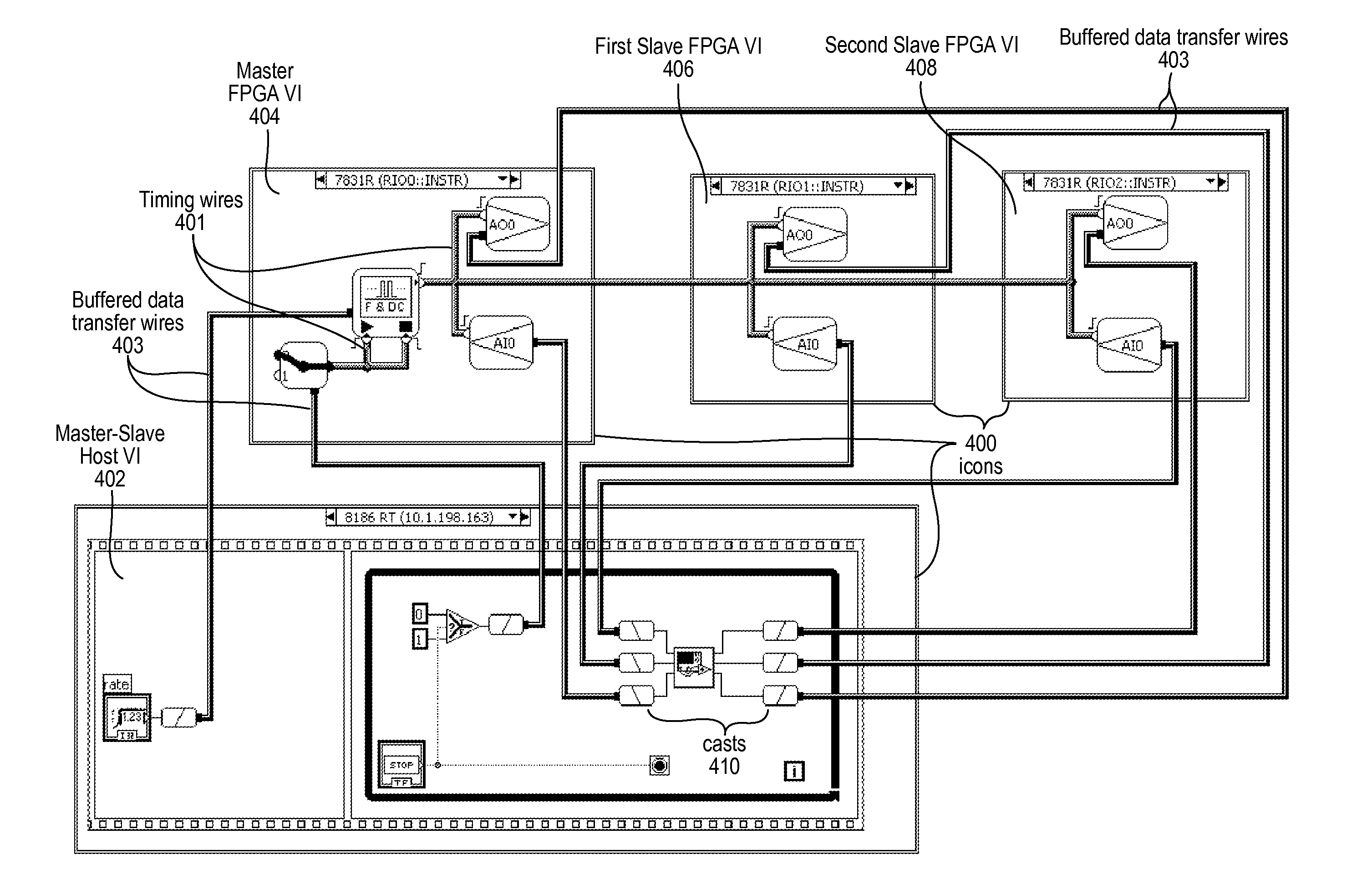
Displaying Physical Signal Routing in a Diagram of a System
a physical signal and system technology, applied in the field of system diagrams, can solve problems such as difficulty for a system designer or user to fully understand
- Summary
- Abstract
- Description
- Claims
- Application Information
AI Technical Summary
Benefits of technology
Problems solved by technology
Method used
Image

Examples
Embodiment Construction
Incorporation by Reference
[0022]The following references are hereby incorporated by reference in their entirety as though fully and completely set forth herein:
[0023]U.S. Pat. No. 4,914,568 titled “Graphical System for Modeling a Process and Associated Method,” issued on Apr. 3, 1990.
[0024]U.S. Pat. No. 5,481,741 titled “Method and Apparatus for Providing Attribute Nodes in a Graphical Data Flow Environment”.
[0025]U.S. Pat. No. 6,173,438 titled “Embedded Graphical Programming System” filed Aug. 18, 1997.
[0026]U.S. Pat. No. 6,219,628 titled “System and Method for Configuring an Instrument to Perform Measurement Functions Utilizing Conversion of Graphical Programs into Hardware Implementations,” filed Aug. 18, 1997.
[0027]U.S. Pat. No. 7,042,469, titled “Multiple Views for a Measurement System Diagram,” filed Dec. 23, 2002.
[0028]U.S. Patent Application Publication No. 2001 / 0020291 (Ser. No. 09 / 745,023) titled “System and Method for Programmatically Generating a Graphical Program in Res...
PUM
 Abstract
Description
Claims
Application Information