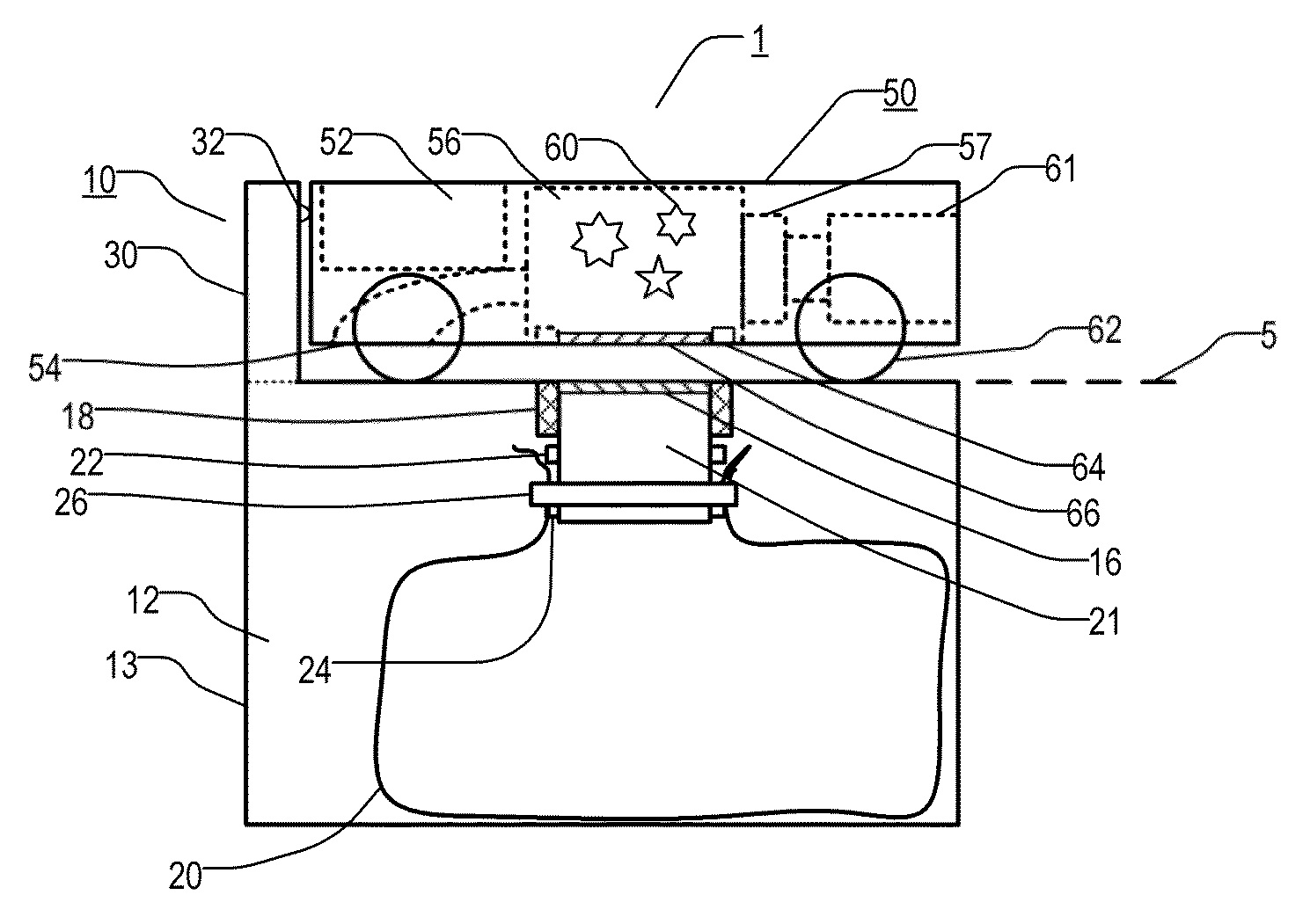
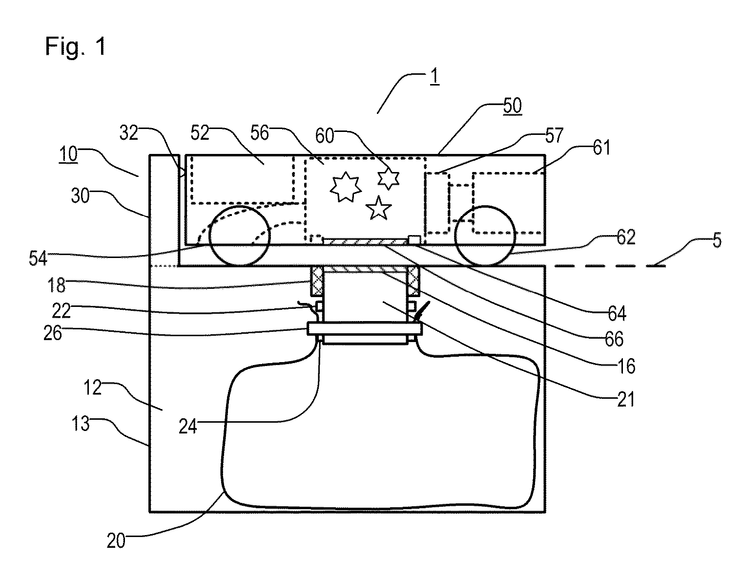
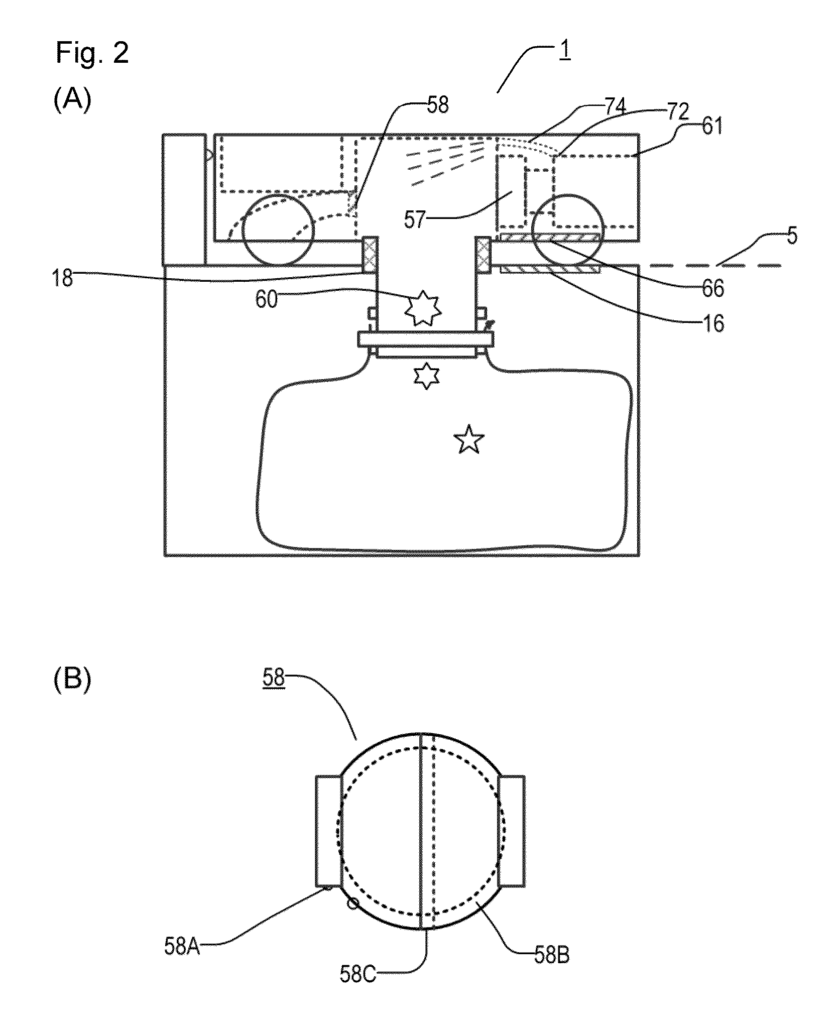
Robot cleaner, dust discharge station, and multi-stage vacuum cleaner

a robot cleaner and dust discharge technology, applied in the field of robot vacuum cleaners, can solve the problems of difficult to discharge dust completely in a multi-stage cyclone cleaner, conventional systems need relatively complex devices inside, etc., and achieve the effect of eliminating the need for frequent dust waste and excellent dust discharg

Active Publication Date: 2013-02-07
LIFE LABO
View PDF3 Cites 39 Cited by
  • Summary
  • Abstract
  • Description
  • Claims
  • Application Information

AI Technical Summary

Benefits of technology

[0012]An objective of the present invention is to solve the above problems (1) to (3) well and to eliminate the need of a frequent dust waste by the user and to provide efficient device for wasting the dust that has been collected in the robot cleaner. The present invention also provides a multi-stage cyclone cleaner that can discharge dust excellently.

Problems solved by technology

The above conventional systems need relatively complex devices inside and apparently need to generate negative pressure in a part of the station to collect dust in the robot cleaner.
Furthermore, it is difficult to discharge dust completely in a multi-stage cyclone cleaner.
Compared with ordinary non-robot vacuum cleaners, there are the following problems associated with a robot cleaner.
(1) need of a frequent dust waste by the user due to small dust capacity

Method used


Image

  • Robot cleaner, dust discharge station, and multi-stage vacuum cleaner
  • Robot cleaner, dust discharge station, and multi-stage vacuum cleaner
  • Robot cleaner, dust discharge station, and multi-stage vacuum cleaner

Examples


second embodiment

[0088](10) Second Embodiment of Multi-Stage Cyclone Cleaner

[0089]FIG. 6B shows a multi-stage cyclone cleaner according to another embodiment, wherein the fan 61A and the motor 61B are located upward of the first and second cyclones 71, 72. Accordingly, the filter 58 is located between the second cyclones 72 and the fan 61A. Axes of the first cyclone 71, the fan 61A, and the motor 61B are substantially identical. This cleaner is advantageous because resistance of air flow at the conduit 75 in FIG. 6A, which is relatively very long and thin, can be decreased, the size of the fan 61A can be increased, and the exhaust air can be directed upwards from a relatively large area.

third embodiment

[0090](11) Third Embodiment of Multi-Stage Cyclone Cleaner

[0091]FIG. 6C shows a multi-stage cyclone cleaner according to another embodiment, wherein the fan 61A is located upward of the first and second cyclones 71, 72 but the motor 61B is located at the center of the first cyclone 71 and under the second cyclones 72. Since there is no need for the space for the motor 61B above the fan 61A, this approach is advantageous in that the overall height can be lowered as compared with the cleaner in FIG. 6B, enabling the cleaner to go into places of low height. However, there is a need for a longer shaft between the motor 61B and the fan 61A, to fix the motor 61B to the cleaner body, to hold the shaft of the motor 61B with respect to the cleaner body, and to protect the shaft, which may be greased, from dust.

[0092]In order to solve the above problems, the cleaner has a motor shaft holder 78A and a motor holder 78B. The motor shaft holder 78A surrounds the motor shaft, which connects the mo...


PUM


Abstract

An objective of the invention is to eliminate the need of a frequent dust waste by the user and to provide efficient device for wasting the dust that has been collected in the robot cleaner. The invention provides a robot cleaner capable of discharging dust out to a dust discharge station, wherein the robot cleaner is capable of moving autonomously to collect dust, the robot cleaner comprising: a dust container for storing dust; a dust inlet for collecting dust into the dust container; and an opening and closing mechanism of the dust container, provided at a bottom surface of the robot cleaner, for discharging dust collected in the dust container.

Description

CROSS-REFERENCE TO RELATED APPLICATIONS[0001]This application claims benefit of a Provisional Application No. 61 / 367,723, filed on Aug. 1, 2010.FIELD OF THE INVENTION[0002]The present invention relates to a robot vacuum cleaner capable of discarding ash easily and a dust discharge station thereof.BACKGROUND ART[0003]A robot cleaner cleans floors in a house autonomously and is expected to be a very useful device that may replace a substantial portion of conventional non-robot vacuum cleaners. Conventional systems are proposed which deal with wasting dust in robot cleaners.[0004]U.S. Pat. No. 5,787,545 describes a system including a discharge unit for discharging dust from a robot cleaner. U.S. Pat. No. 7,053,578 describes a system that discharges dust from the bottom of the robot cleaner using a suction-extraction assembly that generates negative pressure in a charging station. U.S. Pat. Nos. 6,076,226 and 6,327,741 describe systems that collect dust from above the robot cleaner driv...

Claims


Application Information

Patent Timeline
Patent Type & Authority Applications(United States)
IPC IPC(8): A47L13/50A47L9/00B08B7/04
CPCA47L9/106A47L2201/024A47L9/14
Inventor OTA, TETSU
Owner LIFE LABO
Why Eureka
Try Eureka