Method for operating gas separation device

a gas separation and gas technology, applied in the direction of hydrogen separation using solid contact, separation process, membrane, etc., can solve the problems of monogermane, difficult recovery, strong toxicity and combustibility, etc., to achieve efficient separation and recovery, simple detoxification treatment or recycling, and high gas separation performance

Inactive Publication Date: 2013-02-07
NIPPON SANSO CORP +1
View PDF14 Cites 11 Cited by
  • Summary
  • Abstract
  • Description
  • Claims
  • Application Information

AI Technical Summary

Benefits of technology

[0057]According to the method for operating a gas separation device in the invention, when the gas component with a large molecular diameter and the gas component with a small molecular diameter are separated, gas separation can be performed with high gas separation performance and treatment capability in a small number of separation membrane modules. Additionally, since a required number of gas separation membranes are connected in parallel, and are operated while being shifted by a predetermined interval, it is possible to perform continuous separation operation as an overall system.
[0058]According to the method for recovering a residual gas in the invention, the mixed gas remaining in the returned cylinder can be efficiently separated and recovered. This makes it possible to simply perform detoxifying treatment or recycling.

Problems solved by technology

Among these gases, monosilane, monogermane, arsine, phosphine, hydrogen selenide, and the like are gases that have strong toxicity and combustibility and that are very difficult to handle.
In the case of gases that are diluted and mixed with helium or the like, the current situation is that recovery is not performed if the time and effort required for performing separation treatment into dilution gas and specialty gas is considered.
Hydride gases, such as monosilane and monogermane, also have the same problems.
Additionally, even in a case where detoxifying treatment is safely and appropriately performed without performing separation and recovery, particularly, in the case of gases that are diluted and mixed with hydrogen, if these gases are subjected to detoxifying treatment by a combustion detoxifying apparatus, a dry detoxifying apparatus, or the like, there are also problems that combustion heat or reaction heat is much generated under the influence of hydrogen, a burden is imposed on the detoxifying apparatus, safety is unstable, and substantial costs are also incurred.

Method used


Image

  • Method for operating gas separation device
  • Method for operating gas separation device
  • Method for operating gas separation device

Examples


first embodiment

[0075]An example of a form for carrying out the invention will be described below in detail, referring to the drawings.

[0076]An example of a gas separation device used for a method for operating a gas separation device in the invention is shown in FIGS. 1 and 2. In addition, in the example of the gas separation device, a carbon membrane module is used as an example of a separation membrane module. Additionally, in this carbon membrane module, a carbon membrane is used as a gas separation membrane.

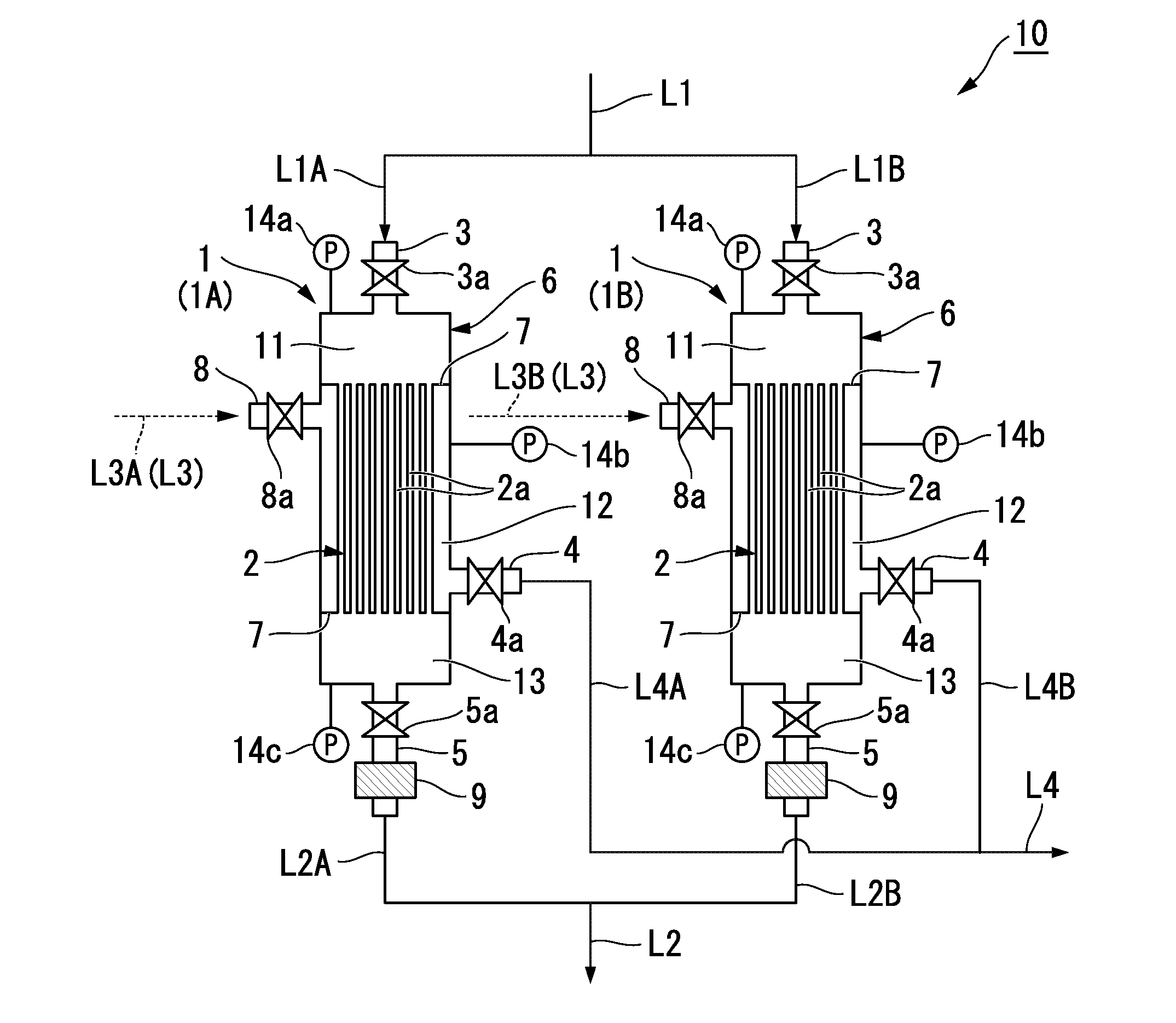
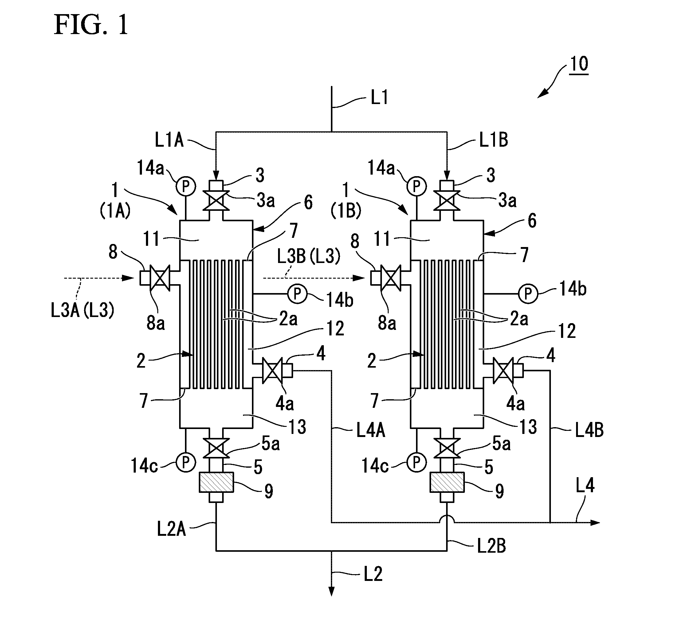
[0077]In FIG. 1, reference numeral 10 designates a gas separation device and reference numeral 1 (1A, 1B) designates a carbon membrane module. The gas separation device 10 is schematically configured such that two carbon membrane modules 1A and 1B are connected in parallel by paths L1 to L4.

[0078]Additionally, the carbon membrane module 1 (1A, 1B) is generally constituted by an airtight container 6 and a carbon membrane unit 2 provided within the airtight container 6.

[0079]The airtight cont...

second embodiment

[0194]A second embodiment to which the invention is applied will be described below in detail with reference to FIGS. 6 and 7.

[0195]An example of a recovery device used for a method for recovering the residual gas that is the second embodiment to which the invention is applied is shown in FIG. 6. In addition, in the example of the recovery device, a carbon membrane module is used as an example of a separation membrane module. Additionally, in this carbon membrane module, a carbon membrane is used as the gas separation membrane.

[0196]As shown in FIG. 6, the recovery device 31 of the present embodiment is schematically configured so as to include a cylinder 21 in which a mixed gas that serves as a target to be separated and recovered remains, a carbon membrane module 220 that separates the mixed gas, and recovery facilities 24 and 25 that recover separated gas components.

[0197]Specifically, the cylinder 21, and a supply port 3 provided in the carbon membrane module 220 are connected t...

third embodiment

[0219]Next, a third embodiment to which the invention is applied will be described. The present embodiment has a configuration different from the method for recovering a residual gas in the second embodiment. For this reason, the method for recovering a residual gas in the present embodiment will be described with reference to FIGS. 8 and 9. As for the recovery device and the carbon membrane module that are used for recovery of a residual gas in the present embodiment, the same constituent portions as the second embodiment are designated by the same reference numerals, and a description thereof is omitted here.

[0220]A recovery device 32 used for the method for recovering a residual gas in the present embodiment shown in FIG. 8 is different from the recovery device 31 in the second embodiment shown in FIG. 6 in that the carbon membrane module 1 is used.

[0221]Additionally, as shown in FIG. 9, the carbon membrane module 1 used for the present embodiment is different from the carbon mem...


PUM

PropertyMeasurementUnit
speedaaaaaaaaaa
speedaaaaaaaaaa
areaaaaaaaaaaa

Abstract

Provided are a method for operating a gas separation device capable of performing gas separation with high separation capability and treatment amount in a small membrane area or in a small number of separation membrane modules, and a method for recovering a residual gas capable of performing more suitable detoxifying treatment or recycling by efficiently separating and recovering a mixed gas remaining in a cylinder, using the operating method. Two or more separation membrane modules are connected with each other in parallel. One separation membrane module is continuously and repeatedly operated in an operation cycle including: a first process for supplying a mixed gas into an airtight container and filling the airtight container with pressure; a second process for, when a predetermined time has elapsed or a predetermined pressure has been reached, stopping the supply of the mixed gas and retaining the supplied mixed gas; a third process for, when a predetermined time has elapsed or a predetermined pressure has been reached, recovering the mixed gas from a non-permeated gas discharge port; and a fourth process for, when a predetermined time has elapsed or a predetermined pressure has been reached, closing the non-permeated gas discharge port. The other separation membrane modules are operated in operation cycles shifted by respective predetermined intervals.

Description

TECHNICAL FIELD[0001]The present invention relates to a method for operating a gas separation device, and a method for recovering a residual gas using the same.[0002]Priority is claimed on Japanese Patent Application Nos. 2010-101385 and 2010-101386, filed Apr. 26, 2010, the content of which is incorporated herein by reference.BACKGROUND ART[0003]Currently, various gases including hydride gases, such as monosilane, monogermane, arsine, phosphine, and hydrogen selenide, are representatively present in specialty gases used for the semiconductor field. Among these gases, monosilane, monogermane, arsine, phosphine, hydrogen selenide, and the like are gases that have strong toxicity and combustibility and that are very difficult to handle.[0004]Particularly, although hydride gases are used as high-purity gases by themselves, hydride gases are also widely used as mixed gases diluted with gases, such as hydrogen or helium.[0005]Here, it is known that, for example, a mixed gas diluted with ...

Claims


Application Information

Patent Timeline
Patent Type & Authority Applications(United States)
IPC IPC(8): B01D53/22B01D71/02
CPCB01D53/22B01D2257/11B01D2311/13B01D2317/022B01D2319/04C01B3/503C01B23/0042C01B2210/0029C01B2210/0037C01B2210/0039C01B2210/004C01B2210/0079C01B2210/0053B01D2257/108B01D71/021C01B3/56B01D53/228B01D53/227B01D71/0213B01D71/0281B01D61/58B01D2311/16
Inventor MIYAZAWA, YUZURUAOMURA, YOKOKOBAYASHI, YOSHIHIKOHARAYA, KENJIYOSHIMUNE, MIKI
Owner NIPPON SANSO CORP
Why Eureka
Try Eureka