Heat dissipation module and LED illumination device using the same

a heat dissipation module and led illumination technology, applied in semiconductor devices, light sources, light sources, etc., can solve the problems of affecting the reliability of led illumination devices, requiring the fins to be extremely thin, deformation or even breakage,

Inactive Publication Date: 2013-02-07
FURUI PRECISE COMPONENT (KUNSHAN) CO LTD +1
View PDF1 Cites 0 Cited by
  • Summary
  • Abstract
  • Description
  • Claims
  • Application Information

AI Technical Summary

Problems solved by technology

However, a lot of heat is generated during the work of the LEDs , which, if not adequately addressed, impacts the reliability of the LED illumination device.
However, the increase of the fins requires the fins to be extremely thin.
The extremely thin fins are easy to deform or even break,

Method used


Image

  • Heat dissipation module and LED illumination device using the same
  • Heat dissipation module and LED illumination device using the same
  • Heat dissipation module and LED illumination device using the same

Examples


Embodiment Construction

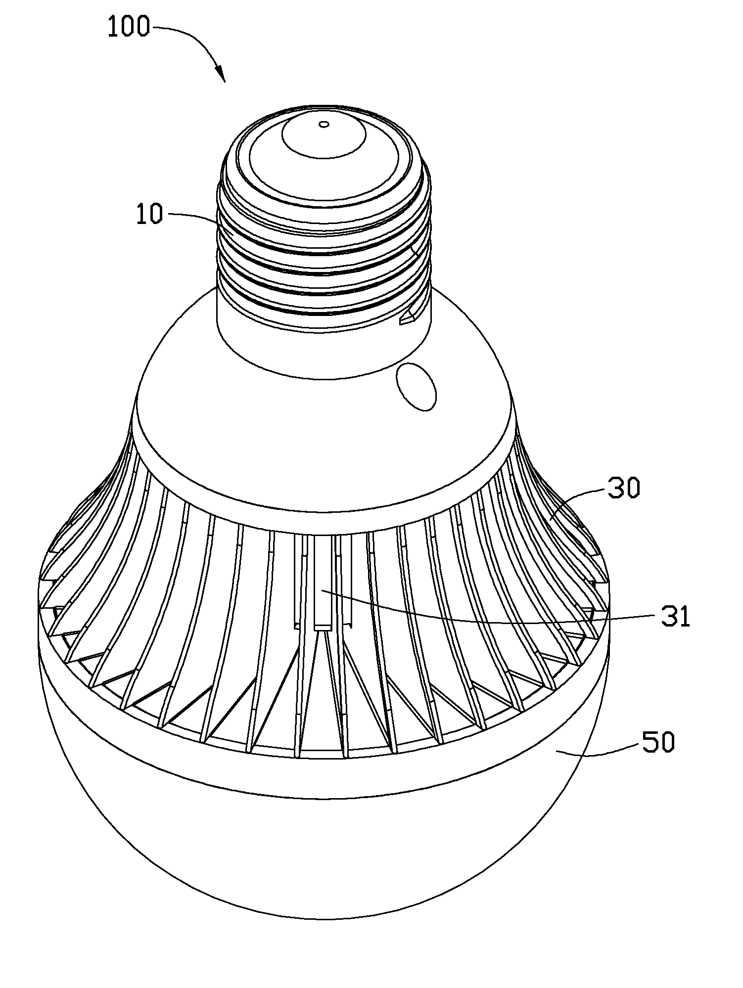
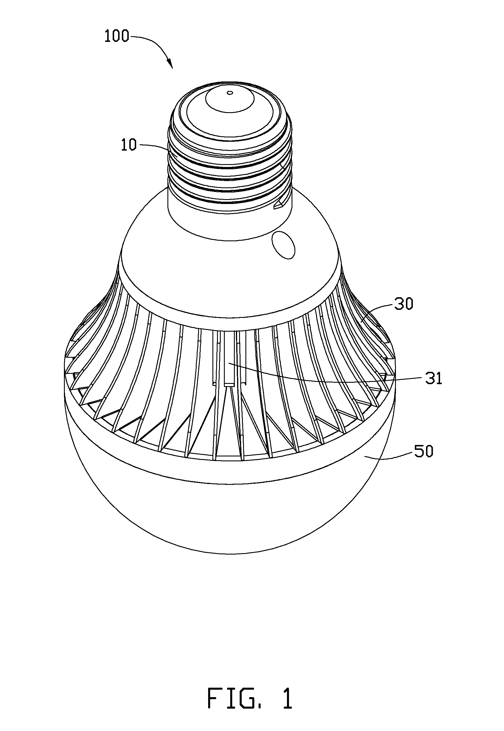
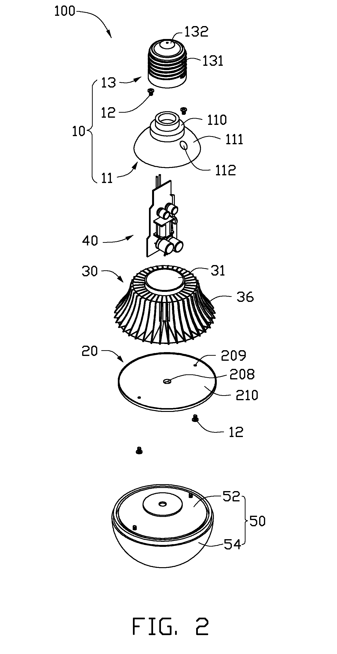
[0012]Referring to FIGS. 1, 2 and 3, an LED illumination device 100 in accordance with an embodiment of the present disclosure comprises a holder 10 for connecting with a power source (not shown), a power module 40, a heat dissipation module 30, an LED module 20 with a top end connecting with the heat dissipation module 30 and a bottom end connecting with an envelope 50.

[0013]The holder 10 comprises a conducting portion 13 and a connecting portion 11 extending downwardly from the conducting portion 13. The conducting portion 13 has a columned shape. Threads 131 are formed on an outer surface of the conducting portion 13. A conducting pad 132 is formed on a top end of the conducting portion 13. The conducting portion 13 is configured for connecting the power source to provide a power for the LED illumination device 100. The connecting portion 11 comprises a connecting bar 110 and a connecting bowl 111 extending downwardly from the connecting bar 110. The connecting bar 110 inserts in...


PUM


Abstract

A heat dissipation module includes a plurality of fins. Each fin includes a main body, a bottom bending plate bending from a bottom edge of the main body, a top bending plate bending from a top edge of the main body, and a slick flange folding inwards from an outer edge of the main body. The flange overlaps the main body at the outer edge of a corresponding fin. The present disclosure also relates to an LED illumination device using the heat dissipation module.

Description

BACKGROUND[0001]1. Technical Field[0002]The present disclosure relates generally to illumination devices, and more particularly to an LED illumination device having a heat sink.[0003]2. Description of Related Art[0004]LEDs as a source of LED illumination devices provide advantages such as resistance to shock and nearly limitless lifetime under specific conditions.[0005]However, a lot of heat is generated during the work of the LEDs , which, if not adequately addressed, impacts the reliability of the LED illumination device. A typical way of providing an LED illumination device with good heat dissipation capability is increasing the pluralitys of fins in the LED illumination device. However, the increase of the fins requires the fins to be extremely thin. The extremely thin fins are easy to deform or even break, which not only impairs the heat dissipation capability of the light fixture, but also destroys the aesthetics of the light fixture. In addition, the extremely thin fins are s...

Claims


Application Information

Patent Timeline
IPC IPC(8): F21V29/00
CPCF21V29/004F21Y2101/02F21Y2105/001F21V3/00F21V29/89F21V23/006F21V23/009F21V29/75F21V29/773F21K9/1355F21Y2105/10F21K9/232F21Y2115/10F21K9/238
Inventor XIA, BEN-FANHWANG, CHING-BAIHUNG, JUI-WEN
Owner FURUI PRECISE COMPONENT (KUNSHAN) CO LTD
Why Eureka
Try Eureka