Pneumatic Tire Valve Snap Fastener Cap and Method of Using Same

a technology of pneumatic tire valve and snap fastener, which is applied in the direction of functional valve types, machines/engines, positive displacement liquid engines, etc., can solve the problems of inconvenient removal of all valve caps on tires, etc., and achieves the effect of preventing the loss of individual valve stem caps, ensuring tire pressure, and appropriately inflating tires

Inactive Publication Date: 2013-02-14
ALLEN RON
View PDF13 Cites 1 Cited by
  • Summary
  • Abstract
  • Description
  • Claims
  • Application Information

AI Technical Summary

Benefits of technology

[0008]With the foregoing in mind, it is an object of the invention to provide a novel tire valve system that will permit the user to efficiently check tire pressure and appropriately inflate the tires on the vehicle without having to remove all of the valve caps on the tires.
[0009]Another object of the invention is to provide a novel tire valve system that permits the user to check tire pressure and appropriately inflate the tires on the vehicle in a convenient manner that prevents the loss of individual valve stem caps and prevents having to either replace the valve stem caps or leave the valve stems exposed to the adverse elements of the weather.
[0010]Another object of the invention is to provide a novel tire valve system of the aforementioned character that permits the user to check tire pressure and appropriately inflate the tires on the vehicle in a rapid and efficient manner.
[0011]Another object of the invention is to provide a novel tire valve system of the character described in the preceding paragraphs that is easy to use, inexpensive to manufacture, and one that enables the user to keep the vehicle tires properly inflated to thereby achieve maximum fuel economy.

Problems solved by technology

While this approach has been the standard for decades, there are problems that present themselves with these standard caps.
One such problem is the inconvenience of having to remove all of the valve caps on tires before checking pressure and / or inflating the tires.
This step can lead to the loss of individual valve stem caps, and having to either replace them or leave the valve stems exposed to all of the elements of the weather, such as water, mud, dirt, and any related problems associated with roadway surfaces.
Also, in the present world of self-service fueling stations, where coin-operated air pumps are the norm, speed is of the essence, meaning that having to unscrew four valve stem caps and avoid losing them is one more frustration to deal with.

Method used


Image

  • Pneumatic Tire Valve Snap Fastener Cap and Method of Using Same
  • Pneumatic Tire Valve Snap Fastener Cap and Method of Using Same
  • Pneumatic Tire Valve Snap Fastener Cap and Method of Using Same

Examples


Embodiment Construction

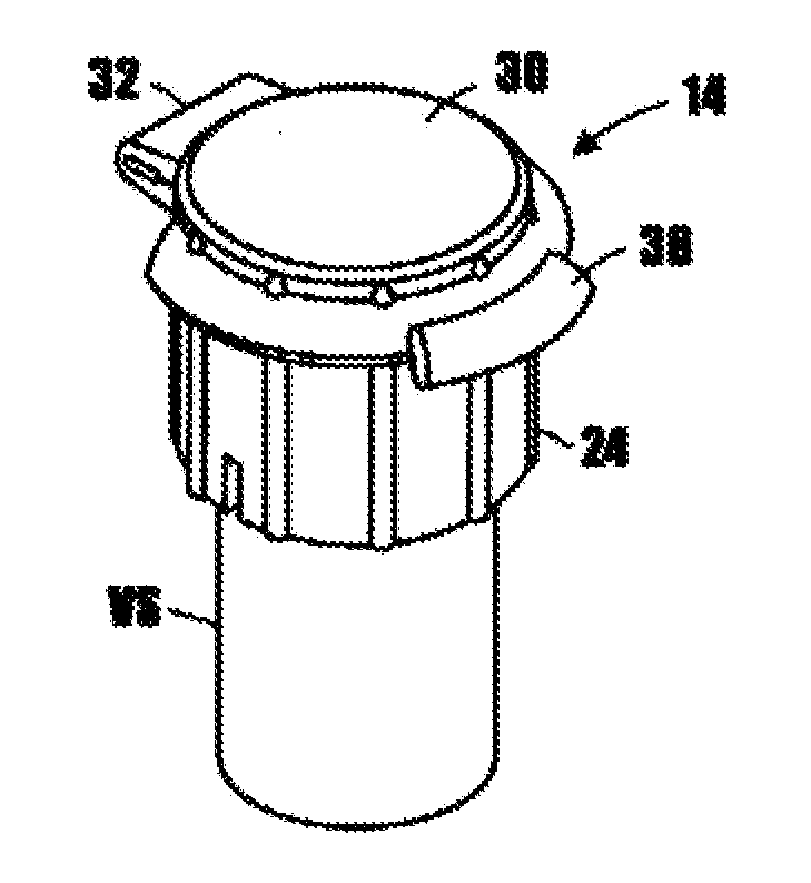
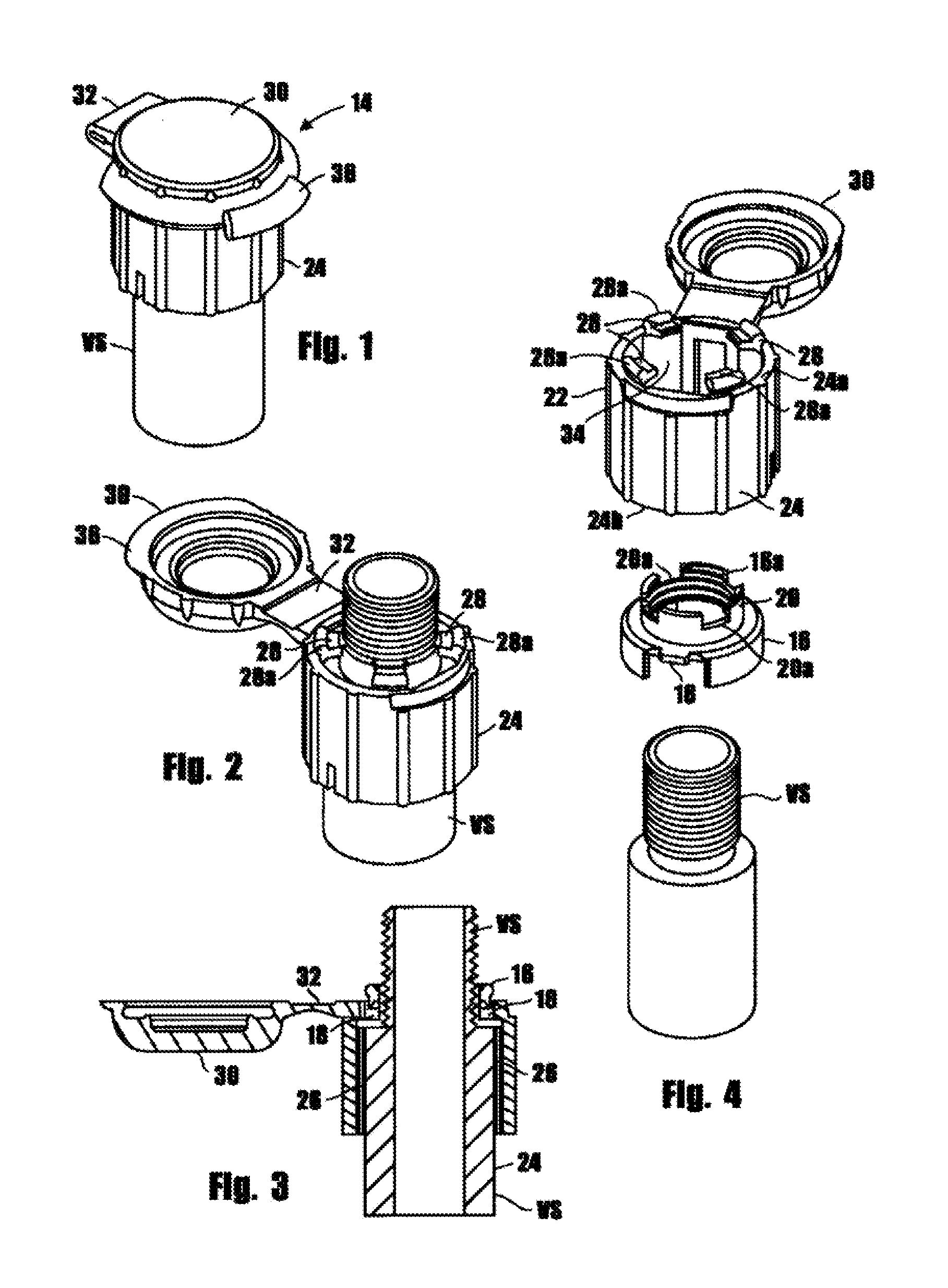
[0025]Referring now to the drawings and particularly FIGS. 1-4, one form of the tire valve stem cap assembly of the invention is there shown and generally designated by the numeral 14. Cap assembly 14 here comprises a lower metal member 16 that is provided with threads 16a to facilitate attachment to the upper threaded portion of a tire valve stem “VS” of the character well known in the art. Lower member 16 includes a pair of diametrically opposed, radially outwardly extending guide tabs 18 and an upstanding, reduced diameter portion 20 that is provided with a plurality of circumferentially spaced slots 20a. Cap assembly 14 further comprises an upper member 22 that includes a skirt 24 having an upper portion 24a and a lower portion 24b. Skirt 24 has a pair of diametrically opposed, internal guide grooves 26 that each receive one of the pair of radially outwardly extending guide tabs 18 so as to guide the downward travel of the upper member 22 over the lower member 16 into the positi...


PUM

PropertyMeasurementUnit
air pressureaaaaaaaaaa
pressureaaaaaaaaaa
speedaaaaaaaaaa

Abstract

A universal valve cap for pneumatic tire valve stems allows for quick and easy access to replenish air in tires. The bottom portion of the cap has an inner thread design, engagable with the threaded valve stem, and the top or crown part of the cap has a snap fastener fitting, allowing for inflation of the tire. The upper portion of the cap has a compression spring or memory plastic that offers resistance to a compressive force that will enable the upper section of the cap to be pressed down over the stationary bottom half of the cap when pressure is applied. The bottom portion of the cap can be pushed down and locked into an open position when inserting air or checking tire pressure. A twist of the cap releases the upper portion to its original position, allowing the top of the cap to be snapped closed.

Description

CROSS-REFERENCE TO RELATED APPLICATIONS[0001]This is a Non-Provisional Application claiming the benefit of co-pending Provisional Application No. 61 / 523,128 filed Aug. 12, 2011.STATEMENT REGARDING FEDERALLY SPONSORED RESEARCH OR DEVELOPMENT[0002]Not ApplicableINCORPORATION-BY-REFERENCE OF MATERIAL SUBMITTED ON A COMPACT DISC[0003]Not ApplicableBACKGROUND OF THE INVENTION[0004]All pneumatic tire valve stems, whether for automobiles, bicycles, or any other vehicle utilizing pneumatic tires, are utilized whenever tires are replaced or for maintaining proper tire inflation pressure. Currently, a fairly generic cap, having, screw threads for engaging complementary threads on the tip of the valve stem, is used to cover and protect the stem portion of the valve. While this approach has been the standard for decades, there are problems that present themselves with these standard caps. One such problem is the inconvenience of having to remove all of the valve caps on tires before checking pr...

Claims


Application Information

Patent Timeline
Patent Type & Authority Applications(United States)
IPC IPC(8): F16L55/115B23P6/00
CPCF04B33/005Y10T29/49407B60C29/066Y10T137/374
Inventor ALLEN, RON
Owner ALLEN RON
Why Eureka
Try Eureka