Wearable antenna assembly for an in-VIVO device

Active Publication Date: 2013-02-14
GIVEN IMAGING LTD
View PDF3 Cites 7 Cited by
  • Summary
  • Abstract
  • Description
  • Claims
  • Application Information

AI Technical Summary

Benefits of technology

[0013]Each of the antenna elements formed in the posterior base may have an orientation that may be defined with respect to the lateral line, and the orientations of the antenna elements may be optimized to maximize signal reception.
[0014]The anterior antenna assembly may include a flat, electrically insulating, anterior lateral base having a lateral line, and n antenna elements that may be formed, for example side-by-side, in the anterior lateral base along the lateral line. Eac

Problems solved by technology

The length and anatomically-inhomogeneous nature of the GI system—it is about five meters long and it has anatomically distinct sections such as the small intestine and the large intestine—and the way in which the GI tract is situated within the body tends to detrimentally affect wireless communication between the in-vivo device and the external receiver when the in-vivo device reaches certain locations within the GI tract.
This detrimental effect, in part, results from the relatively low transmission power that an autonomous, self-contained, in-vivo device uses, and also because body tissues (e.g., muscle tissues, tissues of the GI organs, bone tissue, etc.) interfere with the communication.
A poor communication channel may result in noisy communication and even in loss of data (e.g., image data).
For example, the in-vivo device may transmit an image but, in a poor communication environment, the receiver might not receive the image.
The communication problem described above is further exacerbated by the massive bone structure of the pelvis that supports the GI organs (e.g., the small intestine, the large intestine) and is even less pervious to radio waves than the soft body tissues.
However, the detrimental effect of the pelvis bones on the communication's quality

Method used


Image

  • Wearable antenna assembly for an in-VIVO device
  • Wearable antenna assembly for an in-VIVO device
  • Wearable antenna assembly for an in-VIVO device

Examples


Example

[0032]The description that follows provides various details of exemplary embodiments. However, this description is not intended to limit the scope of the claims but instead to explain various principles of the invention and the manner of practicing it.

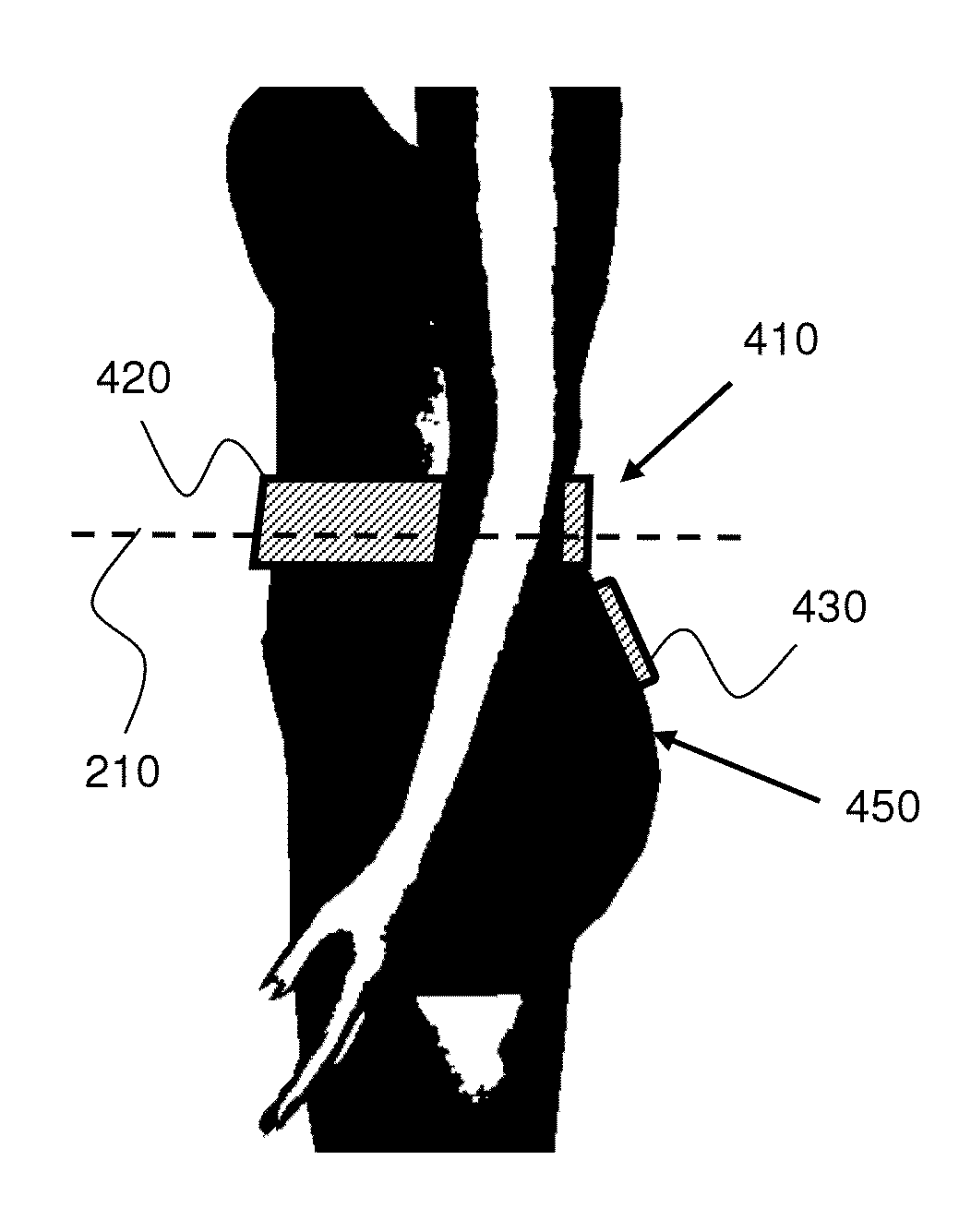
[0033]In an adult male human, the GI tract is 5 meters long in a live subject, or up to 9 meters without the effect of muscle tone, and consists of the upper GI tract and the lower GI tract. The GI tract may also be divided into foregut, midgut, and hindgut. The upper GI tract generally includes the esophagus, stomach, and duodenum. With respect to the GI system the exact demarcation between “upper” and “lower” can vary according to the used convention. The lower GI tract includes most of the small intestine and all of the large intestine.

[0034]When an in-vivo device traverses the GI system, it may move through the lower GI tract passively or controllably. The lower GI tract, which includes most of the small intestine and all of the la...


PUM


Abstract

A wearable antenna assembly includes a posterior antenna assembly and an anterior antenna assembly. The posterior antenna assembly may include a posterior base that includes a lateral portion having a lateral line, and one or two protrusions that continue from the lateral portion and extend away from it, and one or more antenna elements that are formed in the respective protrusion. The protrusions may be configured such that each antenna element lies on the buttocks and is situated adjacent to, or in front of, a greater sciatic notch of the pelvis. The anterior antenna assembly may include an anterior lateral base having a lateral line, and n antenna elements that are formed in the anterior lateral base along the lateral line. The anterior lateral base may be configured such that, when the belt is worn, the n antenna elements are situated adjacent to, or in front of, the abdomen. The orientations of the antenna elements may be optimized to maximize reception of signals originating from a swallowed in-vivo device.

Description

FIELD OF THE INVENTION[0001]The present invention generally relates to an in-vivo sensing system and more specifically to a wearable antenna assembly that facilitates an improved wireless communication between a swallowed in-vivo device and an extra-body receiver or data recorder.BACKGROUND[0002]In-vivo measuring systems are known in the art. Some autonomous capsule like in-vivo devices, which traverse the gastrointestinal (GI) system, may include an imaging sensor, or imager, for imaging (e.g., capturing images or taking pictures of) the interior of the GI system. An in-vivo device may include one or more imagers and / or sensors of other types (e.g., pH sensor, pressure sensor, temperature sensor, etc.), and / or various types of tools (e.g., micro electro-mechanical system, or “MEMS”), for example to perform surgical operations in vivo and / or to administer medication in the GI system, for example from a container contained in an in-vivo device.[0003]While in operation (e.g., after sw...

Claims


Application Information

Patent Timeline
IPC IPC(8): H01Q1/12
CPCH01Q1/44H01Q21/06H01Q9/26A61B1/041H01Q1/48A61B1/00016
Inventor DRUYAN, YOSEFFASTOVSKY, VITALYGILAD, ZVIKA
Owner GIVEN IMAGING LTD
Why Eureka
Try Eureka