Optical mapping apparatus with optimized OCT configuration
a technology of optical mapping apparatus and configuration, which is applied in the field of optical coherence tomography (oct) configuration, can solve the problems of low signal to noise ratio, low optical power delivered to the reference path, and no discussion or contemplation of the influence of splitter splitting ratio on the performance of the system
- Summary
- Abstract
- Description
- Claims
- Application Information
AI Technical Summary
Benefits of technology
Problems solved by technology
Method used
Image
Examples
case 1a
[0190] In the first case, it is assumed that the power of the optical source 50 or 500 is sufficiently small for the shot noise and excess photon noise to be negligible, the OCT configuration has to operate fast, and the power to the object is at the safety limit level.
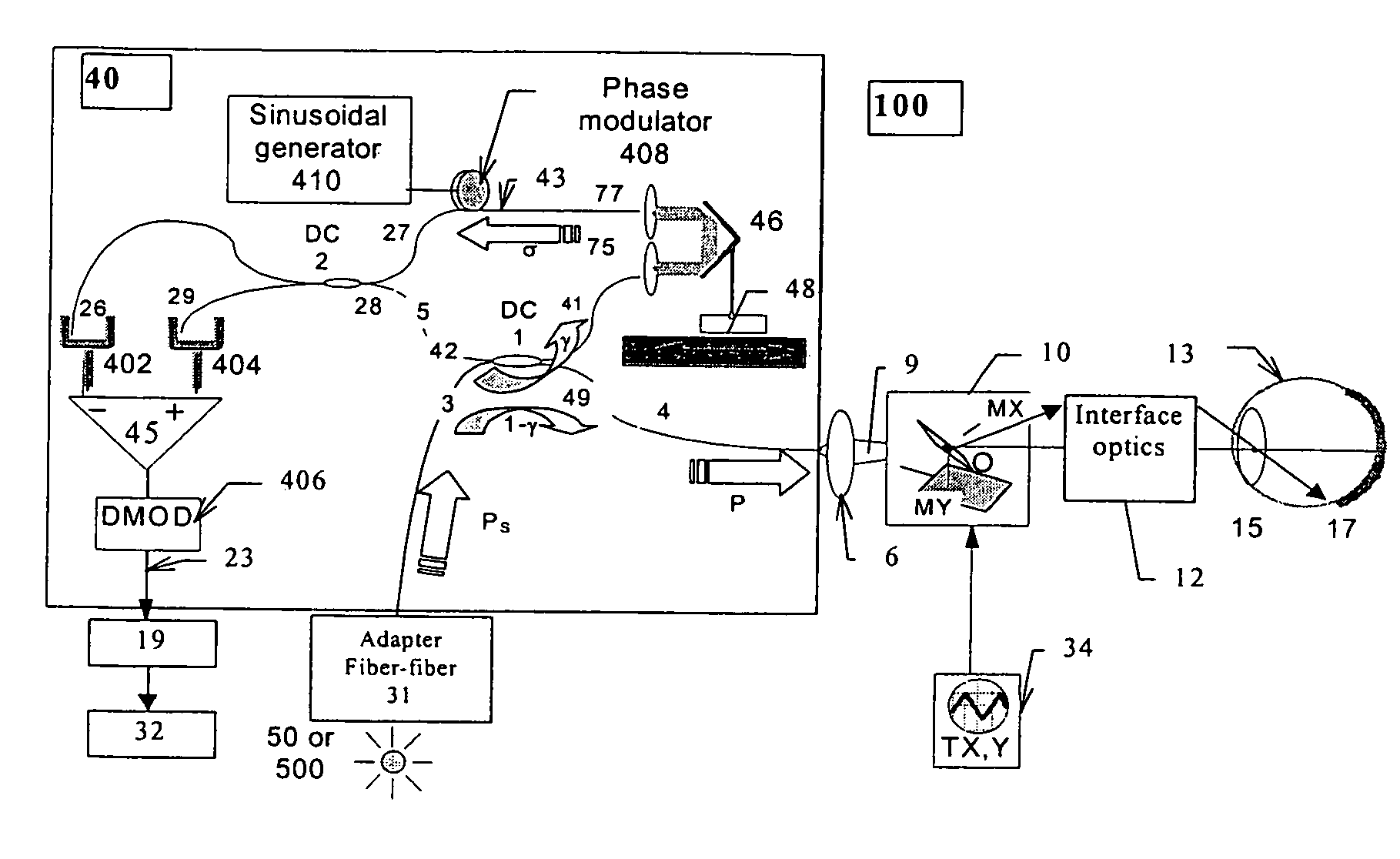
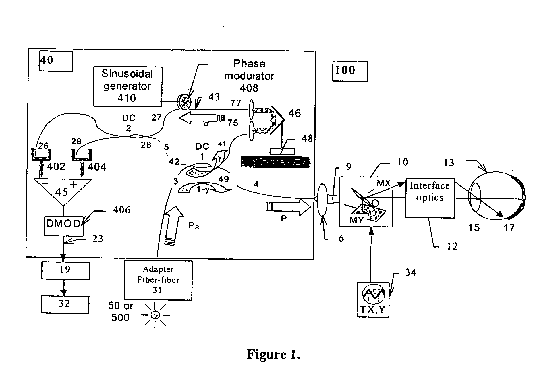
[0191] An example could be a fast OCT apparatus working in A-scan regime for the cornea. In this case, the load resistor RL has to be small for fast acquisition which determines a high thermal noise. At the same time, the beam is not scanned and the safety limit requires for instance in the case of the eye, a few or tens of μW. In this case, the thermal noise ratio becomes: BOSN=GP2C=(α γ)2 P24 kTRL1-γσ(4)
[0192] In order to ensure a high efficiency in using the signal, it is important that the input splitter 1 shall have an optimized splitting ratio of the forward transmission 1−γ, which comes from the input 3 to the output 49, with respect to the cross transmission γ to the reference path output 41. The sig...
case 1b
[0193] In the second case, it is assumed as before that the power of the optical source 50 or 500 is sufficiently small for the shot noise and excess photon noise to be negligible, the OCT configuration has to operate fast, but the optical source is not capable of delivering power to the object up to the safety limit.
[0194] In this case, the condition (4) changes. The source power is Ps: PS=P1-γ(5)
and (2) becomes: BOSN=σ(α γ)2(1-γ) PS24kTRL(6)
[0195] In order to ensure a high efficiency in using the signal, it is important that the input splitter 1 shall have an optimized splitting ratio of the forward transmission 1−γ, which comes from the input 3 to the output 49, with respect to the cross transmission γ to the reference path output 41. Expression (6) has a maximum at γ=⅔, i.e ⅓ from the source power shall be transferred by the optical splitter 1 to the object output port and ⅔ from the source power shall be transferred to the reference output beam.
case 2a
[0196] A third case assumes that the balance detection is ideal, which together with a moderate power safety level makes the shot noise dominate over the excess photon noise, and also that the safety level is as such that the receiver noise can also be neglected in comparison to the shot noise and additionally that the power to the object is at the safety limit level.
[0197] For example, when the power P increases, such as for scanned en-face imaging, where the safety value could be as high as 1 mW to the eye, the receiver noise could be ignored in comparison with the shot noise. DPB in (3c) dominates over CB in (2). When R and m are small, DPB also dominates over AP2 in (2) and the signal to noise ration becomes: BSSN=GPD=α γ Pe(7)
[0198] Again, the larger γ the larger the signal to noise ratio.
[0199] Another case assumes as immediately above that the balance detection is ideal which together with a moderate power safety level makes the shot noise dominate over the excess pho...
PUM
| Property | Measurement | Unit |
|---|---|---|
| wavelengths | aaaaa | aaaaa |
| power | aaaaa | aaaaa |
| coherence length | aaaaa | aaaaa |
Abstract
Description
Claims
Application Information
 - R&D
- Intellectual Property
- Life Sciences
- Materials
- Tech Scout
- Unparalleled Data Quality
- Higher Quality Content
- 60% Fewer Hallucinations
Browse by: Latest US Patents, China's latest patents, Technical Efficacy Thesaurus, Application Domain, Technology Topic, Popular Technical Reports.
© 2025 PatSnap. All rights reserved.Legal|Privacy policy|Modern Slavery Act Transparency Statement|Sitemap|About US| Contact US: help@patsnap.com


