Method and system for optical heterodyne detection of an optical signal that utilizes optical attenuation

Inactive Publication Date: 2005-11-29
AGILENT TECH INC
View PDF4 Cites 1 Cited by
  • Summary
  • Abstract
  • Description
  • Claims
  • Application Information

AI Technical Summary

Benefits of technology

[0007]A method and system for monitoring an optical signal utilizing optical heterodyne detection involves attenuating an input signal before the input signal is combined with a local oscillator signal. The input signal is attenuated in order improve the signal to noise ratio of the heterodyne signal that is generated when the input signal and the local oscillator signal are combined. The signal to noise ratio of the heterodyne signal improves with attenuation of the input signal, specifically in the case where the intensity noise from the input signal is the dominant noise source, because the heterodyne signal and the intensity noise of the input signal scale differently with attenuation of the input signal.
[0010]In an embodiment of the optical heterodyne detection system, the attenuator is adjustable so that the input signal can be attenuated to different levels. Preferably, the attenuator is adjusted to attenuate the input signal to a level that maximizes the signal to noise ratio of the heterodyne signal. In an embodiment, the signal to noise ratio is maximized when the intensity noise of input signal is approximately equal to the shot noise of the local oscillator signal. A feedback loop may be provided between the processor and the adjustable attenuator so that the attenuator can be adjusted in response to real-time measurements of the signal to noise ratio of the heterodyne signal.

Problems solved by technology

For example, grating based OSAs and autocorrelation based OSAs encounter mechanical constraints, such as constraints on beam size and the scanning of optical path lengths, which limit the degree of resolution that can be obtained.
Although balanced detection is useful in improving the signal to noise ratio for the heterodyne signal, it has limitations.
Although amplifying the input signal increases the amplitude of the heterodyne signal, the amplification also increases the intensity noise of the input signal and may not improve the signal to noise ratio of the heterodyne signal.

Method used


Image

  • Method and system for optical heterodyne detection of an optical signal that utilizes optical attenuation
  • Method and system for optical heterodyne detection of an optical signal that utilizes optical attenuation
  • Method and system for optical heterodyne detection of an optical signal that utilizes optical attenuation

Examples


Embodiment Construction

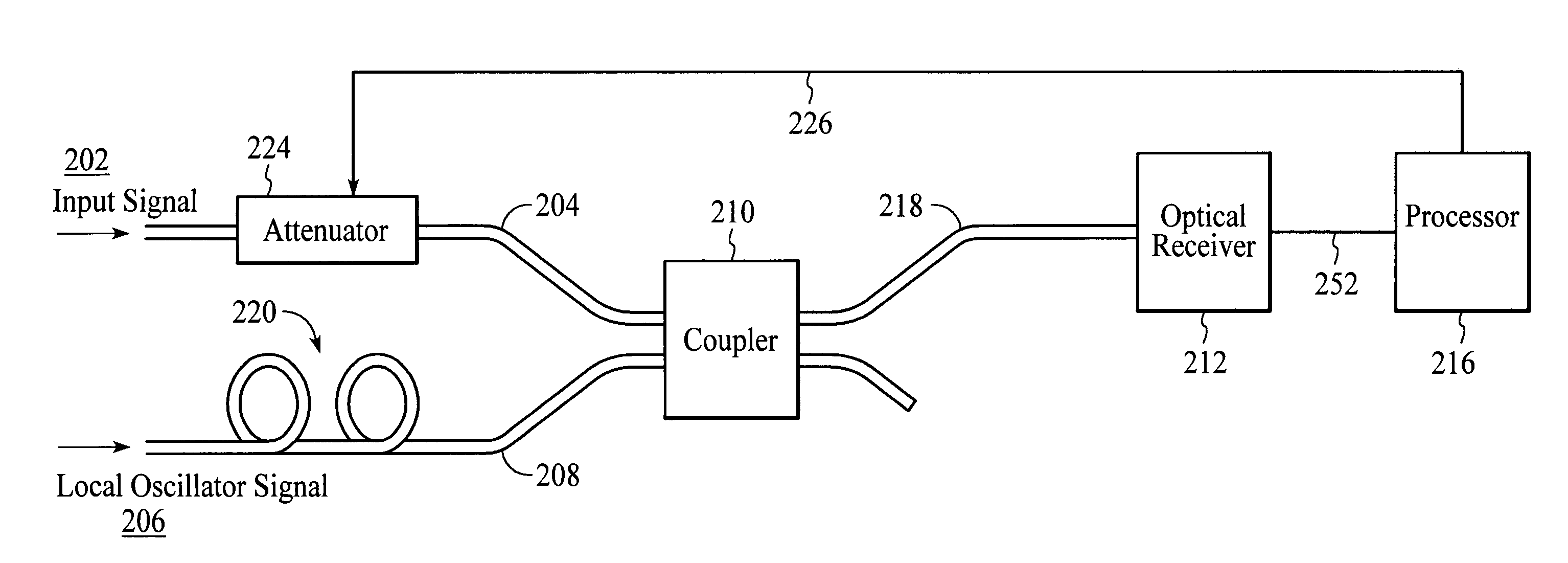
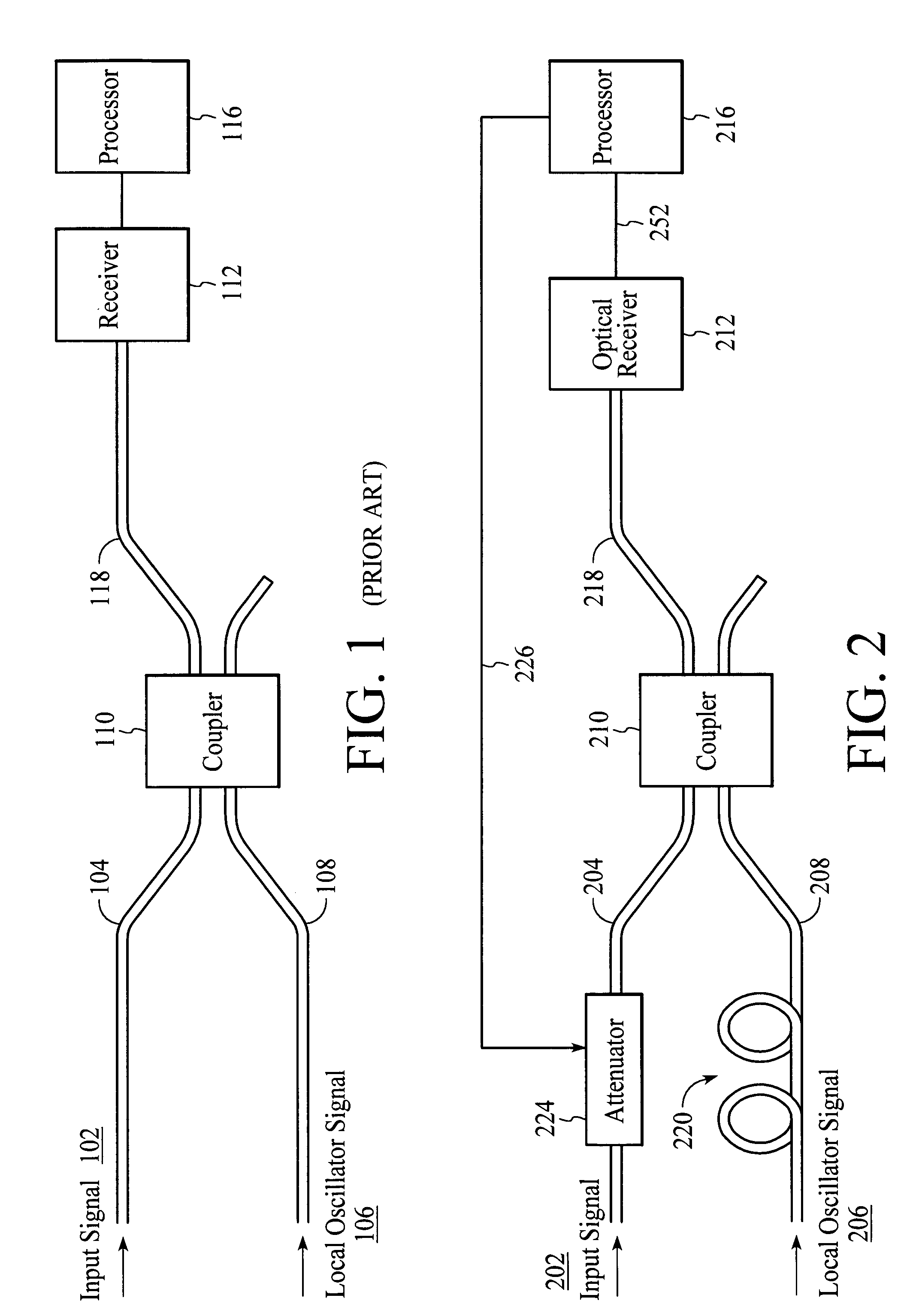
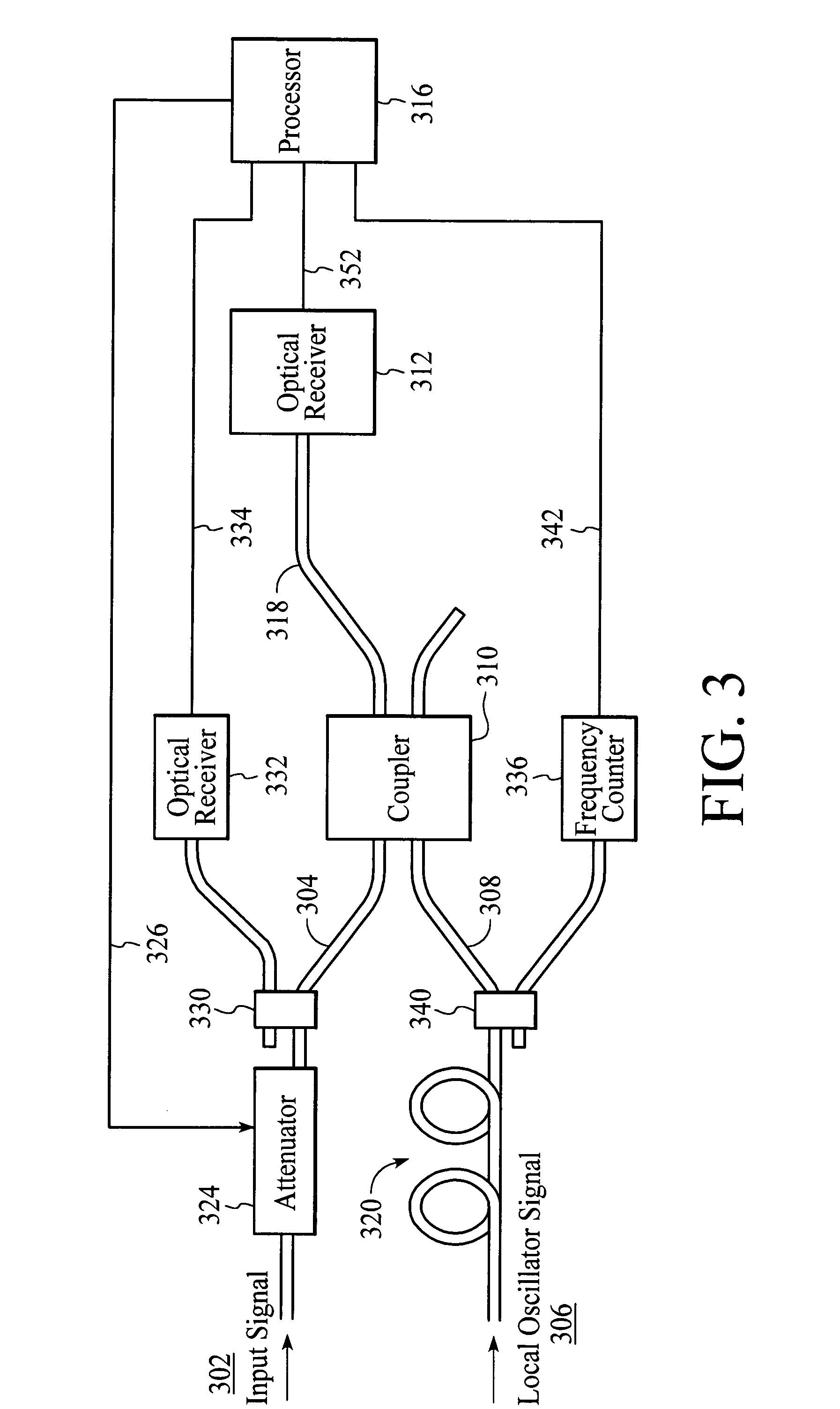
[0019]An embodiment of the invention involves an optical heterodyne detection system in which an input signal is attenuated before the input signal is combined with a local oscillator signal. The input signal is attenuated in order to improve the signal to noise ratio of the heterodyne signal that is generated when the input signal and the local oscillator signal are combined.

[0020]As is known in the field of optical heterodyne detection, an input signal and local oscillator signal combine to create an optical signal having components that include intensity noise from the input signal, shot noise from the local oscillator signal, and the heterodyne signal. When the intensity noise of the input signal is the dominant noise source, attenuating the input signal before the input signal is combined with the local oscillator signal improves the signal to noise ratio of the heterodyne signal. The signal to noise ratio of the heterodyne signal is improved because the intensity noise of the ...


PUM


Abstract

Monitoring an optical signal utilizing optical heterodyne detection involves attenuating an input signal before the input signal is combined with a local oscillator signal. The input signal is attenuated in order improve the signal to noise ratio of the heterodyne signal that is generated when the input signal and the local oscillator signal are combined. The signal to noise ratio of the heterodyne signal improves with attenuation of the input signal, specifically in the case where the intensity noise from the input signal is the dominant noise source, because the heterodyne signal and the intensity noise of the input signal scale differently with attenuation of the input signal.

Description

FIELD OF THE INVENTION[0001]The invention relates generally to the field to optical measurements and measuring systems, and more particularly to a method and system for optical heterodyne detection of an optical signal.BACKGROUND OF THE INVENTION[0002]Dense wavelength division multiplexing (DWDM) requires optical spectrum analyzers (OSAs) that have higher spectral resolution than is typically available with current OSAs. For example, grating based OSAs and autocorrelation based OSAs encounter mechanical constraints, such as constraints on beam size and the scanning of optical path lengths, which limit the degree of resolution that can be obtained.[0003]As an alternative to grating based and autocorrelation based OSAs, optical heterodyne detection systems can be utilized to monitor DWDM systems. FIG. 1 is a depiction of a prior art optical heterodyne detection system. The optical heterodyne detection system includes an input signal 102, an input waveguide 104, a local oscillator sign...

Claims


Application Information

Patent Timeline
IPC IPC(8): H04B10/04H04B10/06G01J9/04H04B10/08H04B10/142H04B10/148H04B10/152H04B17/00
CPCH04B10/60H04B10/64
Inventor SORIN, WAYNE V.BANEY, DOUGLAS M.
Owner AGILENT TECH INC
Why Eureka
Try Eureka