Magnetic and current sensors

A magnetic sensor and bias current technology, which is applied in the direction of measuring current/voltage, instruments, and measuring electrical variables, etc., can solve the problems of non-uniform offset voltage, inconsistent diffusion thickness, and inability to solve the problem of inconsistent deviation of the diffusion thickness of the magnetic sensitive element 10 , to achieve the effect of reducing the effective signal error and improving the signal noise

Active Publication Date: 2018-07-24
上海兴感半导体有限公司
View PDF4 Cites 0 Cited by
  • Summary
  • Abstract
  • Description
  • Claims
  • Application Information

AI Technical Summary

Problems solved by technology

[0004] However, in the prior art, the diffusion thickness of the magnetic sensor 10 at various angles during the diffusion doping process is inconsistent, that is, the non-uniform offset voltage that exists in itself, which will not change due to the change of the direction of the driving current
Therefore, the above-mentioned dynamic offset technology still cannot solve the deviation caused by the inconsistent diffusion thickness of the magnetic sensor 10 itself, and cannot be applied to current sensor products with high precision and high linearity requirements

Method used


Image

  • Magnetic and current sensors
  • Magnetic and current sensors
  • Magnetic and current sensors

Examples


Embodiment Construction

[0014] The specific embodiments of the magnetic sensor and the current sensor provided by the present invention will be described in detail below with reference to the accompanying drawings.

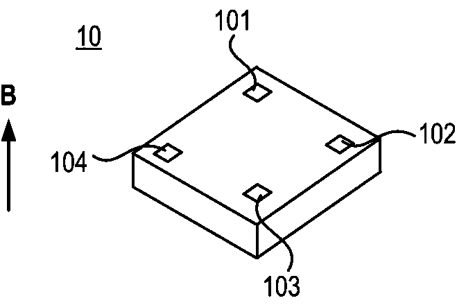
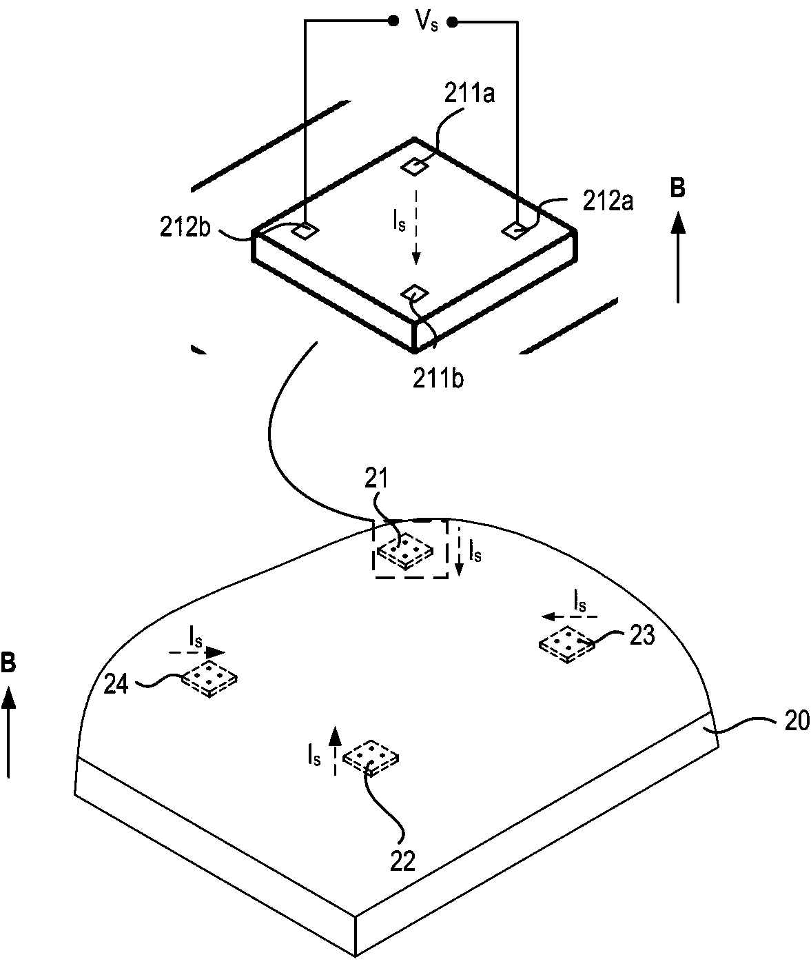
[0015] Attached figure 2 Shown is a schematic diagram of the magnetic sensor structure of the present invention, including a semiconductor substrate 20, a first magnetic sensor 21, a second magnetic sensor 22, a third magnetic sensor 23, and a fourth magnetic sensor on the surface of the semiconductor substrate 20 Sensitive element 24. The first magnetic sensor 21 is provided with a pair of bias electrodes 211a, 211b and a pair of sampling electrodes 212a, 212b. The bias electrodes 211a and 211b have a voltage V s In the case of the magnetic sensor, a bias current I can be introduced s , The sampling electrodes 212a, 212b are used to sample the bias current I s A Hall voltage V generated by working together with an ambient magnetic field B h . Other magneto-sensitive elements are also set...


PUM


Abstract

The invention provides a magnetic sensor and a current sensor. The magnetic sensor comprises a semiconductor substrate, a first magneto sensor, a second magneto sensor, a third magneto sensor and a fourth magneto sensor, wherein the first magneto sensor, the second magneto sensor, the third magneto sensor and the fourth magneto sensor are arranged on the surface of the semiconductor substrate, a pair of bias electrodes and a pair of sampling electrodes are arranged on each magneto sensor, the bias electrodes are used for leading in bias currents on the magneto sensors, the sampling electrodes are used for sampling a Hall voltage generated through combined action of the bias currents and an environmental magnetic field, and the directions of the bias currents on the four magneto sensors are sequentially perpendicular to each other. The magnetic sensor and the current sensor have the advantages that due to the arrangement of the multiple magneto sensors and the currents of the magneto sensors are perpendicular to each other, and deviation caused when diffusion angles of the magneto sensors are not consistent and thicknesses are not consistent can be reduced.

Description

Technical field [0001] The invention relates to the field of integrated circuit design and packaging, in particular to a magnetic sensor and a current sensor. Background technique [0002] The basic principle of the current sensor is to use the electromagnetic induction phenomenon to use a Hall sensor to detect the current through the wire. In the prior art, a Hall sensor is usually used to detect the magnetic field strength. [0003] Attached figure 1 Shown is a schematic diagram of the basic principle of the Hall sensor detecting the magnetic field in the prior art. The four corners of the magnetic sensor 10 are respectively provided with electrodes 101 to 104, and the direction of the magnetic field B is perpendicular to the drawing. At this time, a voltage V is applied to the electrode 101 and the electrode 103 of the magnetic sensor 10 s , Under the action of the Hall effect, the carrier will generate a potential difference V between the electrode 102 and the electrode 104 h...

Claims


Application Information

Patent Timeline
Patent Type & Authority Patents(China)
IPC IPC(8): G01R33/07G01R19/00
Inventor 钟小军
Owner 上海兴感半导体有限公司
Why Eureka
Try Eureka