Optical mapping apparatus with optimized OCT configuration

a technology of optical mapping apparatus and configuration, which is applied in the field of optical coherence tomography (oct) configuration, can solve the problems of low signal to noise ratio, low optical power delivered to the reference path, and no discussion or contemplation of the influence of splitter splitting ratio on the performance of the system

Inactive Publication Date: 2005-08-09
OPTOS PLC
View PDF6 Cites 69 Cited by
  • Summary
  • Abstract
  • Description
  • Claims
  • Application Information

AI Technical Summary

Benefits of technology

[0047]Still further, when the power PS of the light source is sufficiently high that a signal to noise ratio curve thereof versus the optical power therefrom will saturate, then the splitting ratio ε is set high so that the amount of optical power transferred to the object to be scanned is high and the amount of optical power delivered to the reference path is low.
[0048]Thus, an optimum attenuation of power in the reference path is sought so as to maximize the signal to noise ratio.

Problems solved by technology

The two Takada papers noted above each discusses the use of single mode couplers, but because of fiber end reflection there may be significant noise in the OCT system.
However, there is no discussion or contemplation of the influence of splitting ratios of the splitters on the performance of the system.
However, non-reciprocal devices such as circulators are used to route the signal, and those devices are very expensive.
Moreover, there are no such circulators that are presently available which function in wavelengths of about 800 nm, which is a wavelength that is particularly employed in OCT applications relating to the human eye.
A problem which is common to most, if not all, of the patents noted above is that stray reflections may, and usually do, occur in the object arm, a problem which may come as a consequence of fiber end terminations or other elements within the system.
Particular cases of optical coherence tomography, this may cause increased noise as a consequence of excess photon noise.
If light reflected and scattered back from the target is to be monitored, the noise may exceed or even swamp the signal to be monitored.
The WIPO publication discusses equations for determination of excess photon noise coming as a consequence of fiber end reflection, but provides no teachings of how to eliminate such noise.
This limits the applicability of the equations derived.
In practice, at high reference power values, the mismatch in the elements of the balanced receiver contributes to noise more than the noise due to the fiber end reflection.
However, it is been found in practice that the adjustment of two bulk beam splitters is difficult.
It is also well known that broadband light sources used in an OCT apparatus typically have a limited life, and therefore need frequent replacing.
Therefore, such sources—which typically have a pigtail connection—cannot be fused to the input fiber of the OCT apparatus, and an appropriate connector must be selected.
Thus, pigtails are usually terminated with an FC / PC or FC / APC connector which, however, may introduce some losses into the system.
Moreover, there may be reflection back from the connector, which is very detrimental to the SLD, and which at the same time may create a new source of noise.

Method used


Image

  • Optical mapping apparatus with optimized OCT configuration
  • Optical mapping apparatus with optimized OCT configuration
  • Optical mapping apparatus with optimized OCT configuration

Examples


case 1a

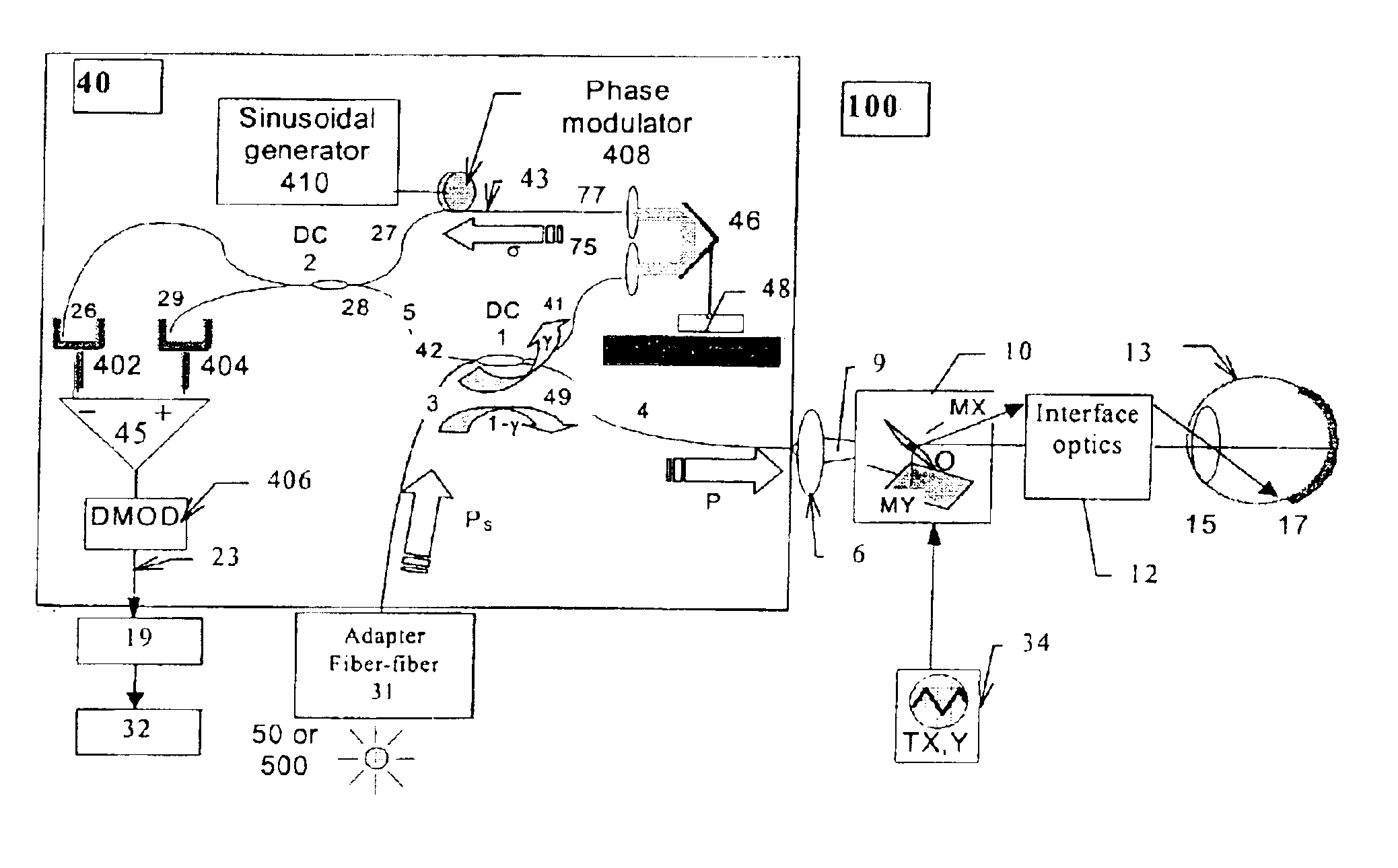
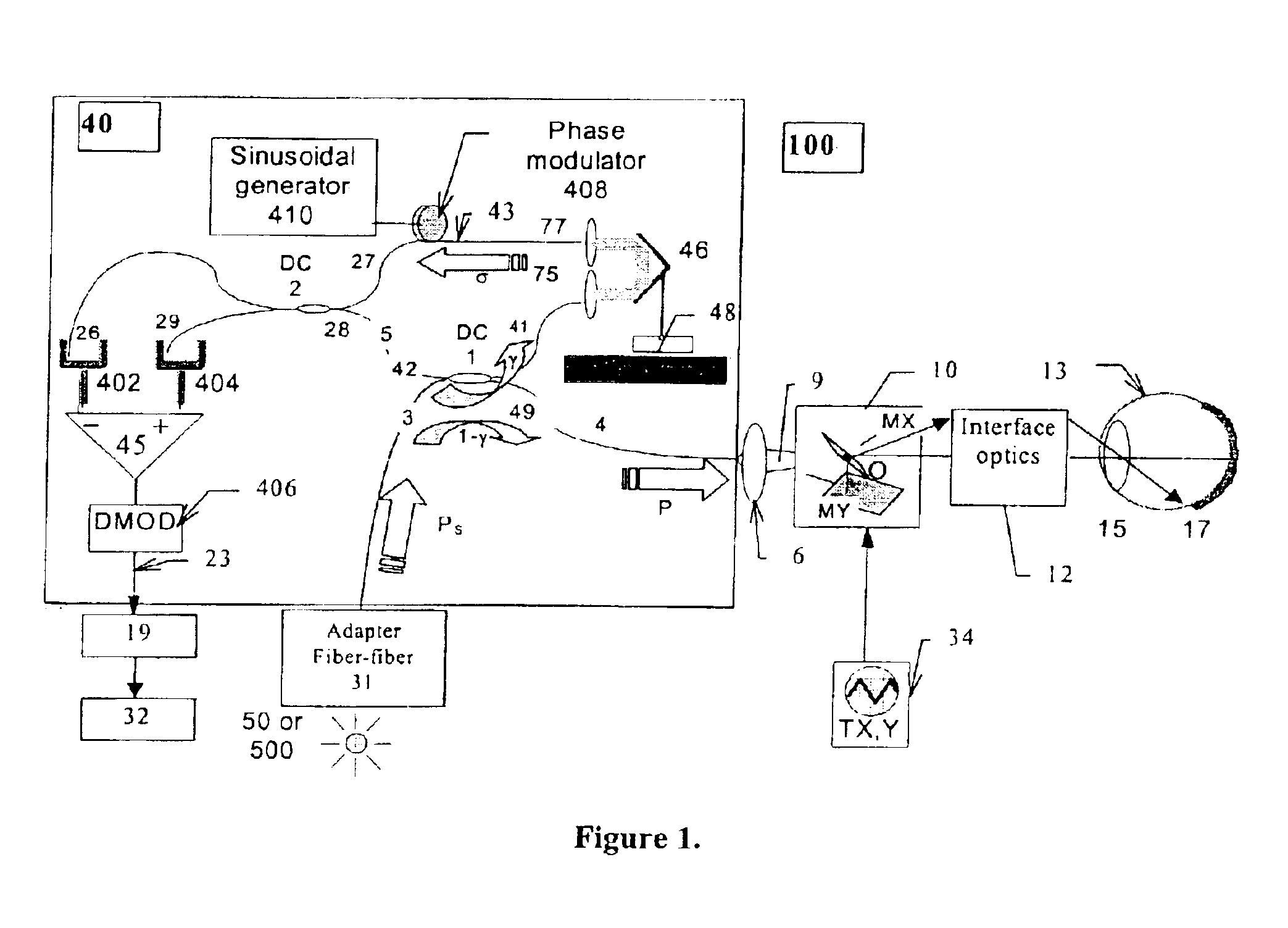
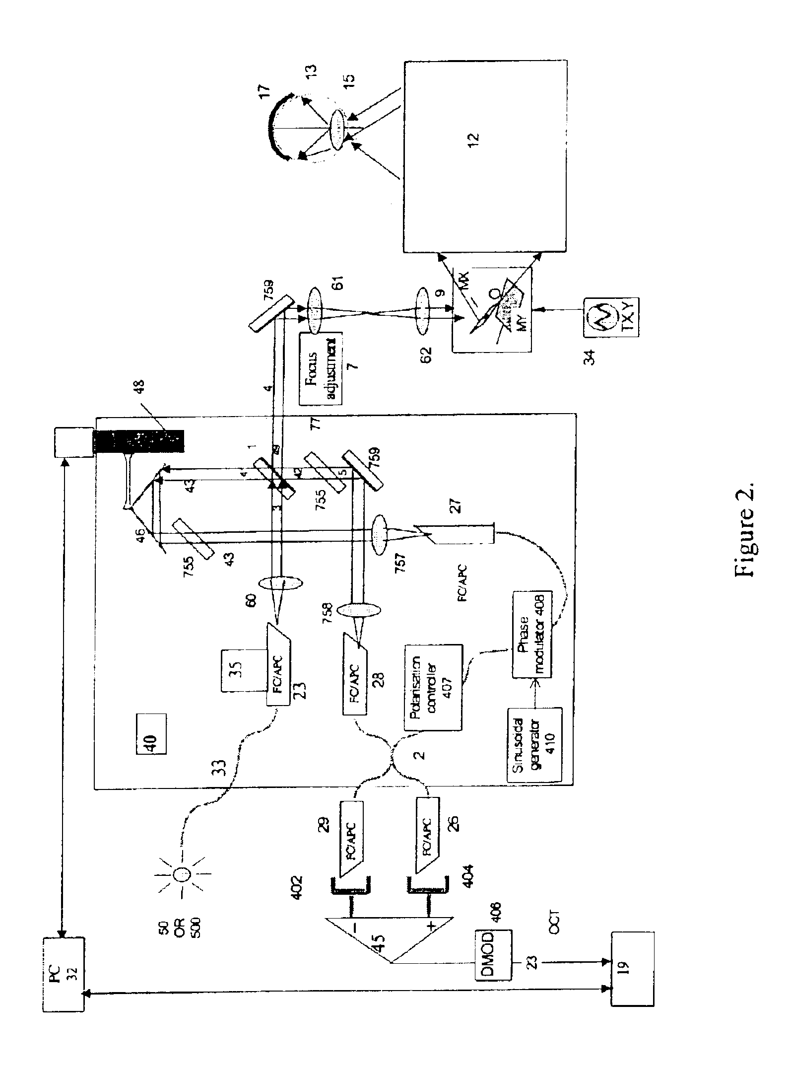
[0179] In the first case, it is assumed that the power of the optical source 50 or 500 is sufficiently small for the shot noise and excess photon noise to be negligible, the OCT configuration has to operate fast, and the power to the object is at the safety limit level.

[0180]An example could be a fast OCT apparatus working in A-scan regime for the cornea. In this case, the load resistor RL has to be small for fast acquisition which determines a high thermal noise. At the same time, the beam is not scanned and the safety limit requires for instance in the case of the eye, a few or tens of μW. In this case, the thermal noise ratio becomes: BO⁢SN=GP2C=(αγ)2⁢P24⁢kTRL⁢1-γσ(4)

[0181]In order to ensure a high efficiency in using the signal, it is important that the input splitter 1 shall have an optimized splitting ratio of the forward transmission 1−γ, which comes from the input 3 to the output 49, with respect to the cross transmission γ to the reference path output 41. The signal to nois...

case 1b

[0182] In the second case, it is assumed as before that the power of the optical source 50 or 500 is sufficiently small for the shot noise and excess photon noise to be negligible, the OCT configuration has to operate fast, but the optical source is not capable of delivering power to the object up to the safety limit.

[0183]In this case, the condition (4) changes. The source power is PS: PS=P1-γ(5)

and (2) becomes: BO⁢SN=σ⁡(αγ)2⁢(1-γ)⁢PS24⁢kTRL(6)

[0184]In order to ensure a high efficiency in using the signal, it is important that the input splitter 1 shall have an optimized splitting ratio of the forward transmission 1−γ, which comes from the input 3 to the output 49, with respect to the cross transmission γ to the reference path output 41. Expression (6) has a maximum at γ=⅔, i.e ⅓ from the source power shall be transferred by the optical splitter 1 to the object output port and ⅔ from the source power shall be transferred to the reference output beam.

case 2a

[0185] A third case assumes that the balance detection is ideal, which together with a moderate power safety level makes the shot noise dominate over the excess photon noise, and also that the safety level is as such that the receiver noise can also be neglected in comparison to the shot noise and additionally that the power to the object is at the safety limit level.

[0186]For example, when the power P increases, such as for scanned en-face imaging, where the safety value could be as high as 1 mW to the eye, the receiver noise could be ignored in comparison with the shot noise. DPB in (3c) dominates over CB in (2). When R and m are small, DPB also dominates over AP2 in (2) and the signal to noise ration becomes: BS⁢SN=GPD=αγ⁢ ⁢Pe(7)

[0187]Again, the larger γ the larger the signal to noise ratio.

[0188]Another case assumes as immediately above that the balance detection is ideal which together with a moderate power safety level makes the shot noise dominate over the excess photon noise...


PUM

PropertyMeasurementUnit
wavelengthsaaaaaaaaaa
poweraaaaaaaaaa
coherence lengthaaaaaaaaaa

Abstract

OCT apparatus includes an interferometer, having an input beam splitter and a 50/50 output splitter. The splitting ratio of the input splitter may be optimized depending on the source power of light source and on the mismatch of the balanced receiver. The input splitter is a plate beam-splitter to minimize the stray reflected light in the interferometer and allow sequential operation of the apparatus in the OCT or in the confocal regime. The switching between the two regimes may be at will, or synchronous with the en-face scanning which results in quasi-simultaneous OCT/confocal imaging or in alternatives frames, confocal and OCT. By using polarization sensitive elements, two channels are provided in each regime, OCT and confocal. The two confocal polarization sensitive channels may allow adjustments of compensators prior to OCT measurements or OCT imaging.

Description

FIELD OF THE INVENTION[0001]This invention relates to optical coherence tomography (OCT) configurations. In particular, the present invention provides configurations for optical mapping apparatus where optimized signal handling, particularly of light beams reflected and scattered back from an object, are easily attainable at reasonable cost.[0002]1. Background of the Invention[0003]There are a number of patents and reports, which are noted below, which teach a variety of two splitter optical coherence tomography configurations. However, a difficulty that arises from nearly all of the prior devices is that there may be significant loss in the optics of the devices, and that there may be significant noise introduced into the device. Low losses in the OCT apparatus are required because of the low amplitude of the signal which is returned from the object or tissue that has been scanned. Moreover, OCT typically employs light sources which have significant bandwidth, giving rise to the pr...

Claims


Application Information

Patent Timeline
Patent Type & Authority Patents(United States)
IPC IPC(8): G01B9/02G01N21/47
CPCA61B3/102G01N21/23G01N21/4795G01B9/0201G01B9/0203G01B9/02027G01B9/02091G01B9/02058G01B9/02063A61B5/0066G01B2290/70G01B2290/45
Inventor PODOLEANU, ADRIAN GH.JACKSON, DAVID A.ROGERS, JOHN A.DOBRE, GEORGE M.CUCU, RADU G.
Owner OPTOS PLC
Why Eureka
Try Eureka