Image sensor unit and image reading apparatus

a technology of image sensor and reading apparatus, applied in the direction of electrical apparatus, pictoral communication, etc., can solve the problems of reading accuracy deterioration, and achieve the effect of uniform illumination distribution

Inactive Publication Date: 2013-02-14
CANON COMPONENTS INC
View PDF2 Cites 35 Cited by
  • Summary
  • Abstract
  • Description
  • Claims
  • Application Information

AI Technical Summary

Benefits of technology

[0007]In view of the circumstances described above, an object of the present invention is to provide an image sensor unit and an image reading apparatus that can provide a uniform illuminance distribution of illumination light emitted to a passage space for an object to be illuminated, such as a bill, in particular, a uniform illuminance distribution in the direction of a normal to a surface to be read of the passing object to be illuminated.

Problems solved by technology

Then, there is a possibility that the illuminance of the reflection light from the bill is nonuniform, and the reading accuracy deteriorates.

Method used


Image

  • Image sensor unit and image reading apparatus
  • Image sensor unit and image reading apparatus
  • Image sensor unit and image reading apparatus

Examples


Embodiment Construction

[0029]In the following, an embodiment of the present invention will be described in detail with reference to the drawings.

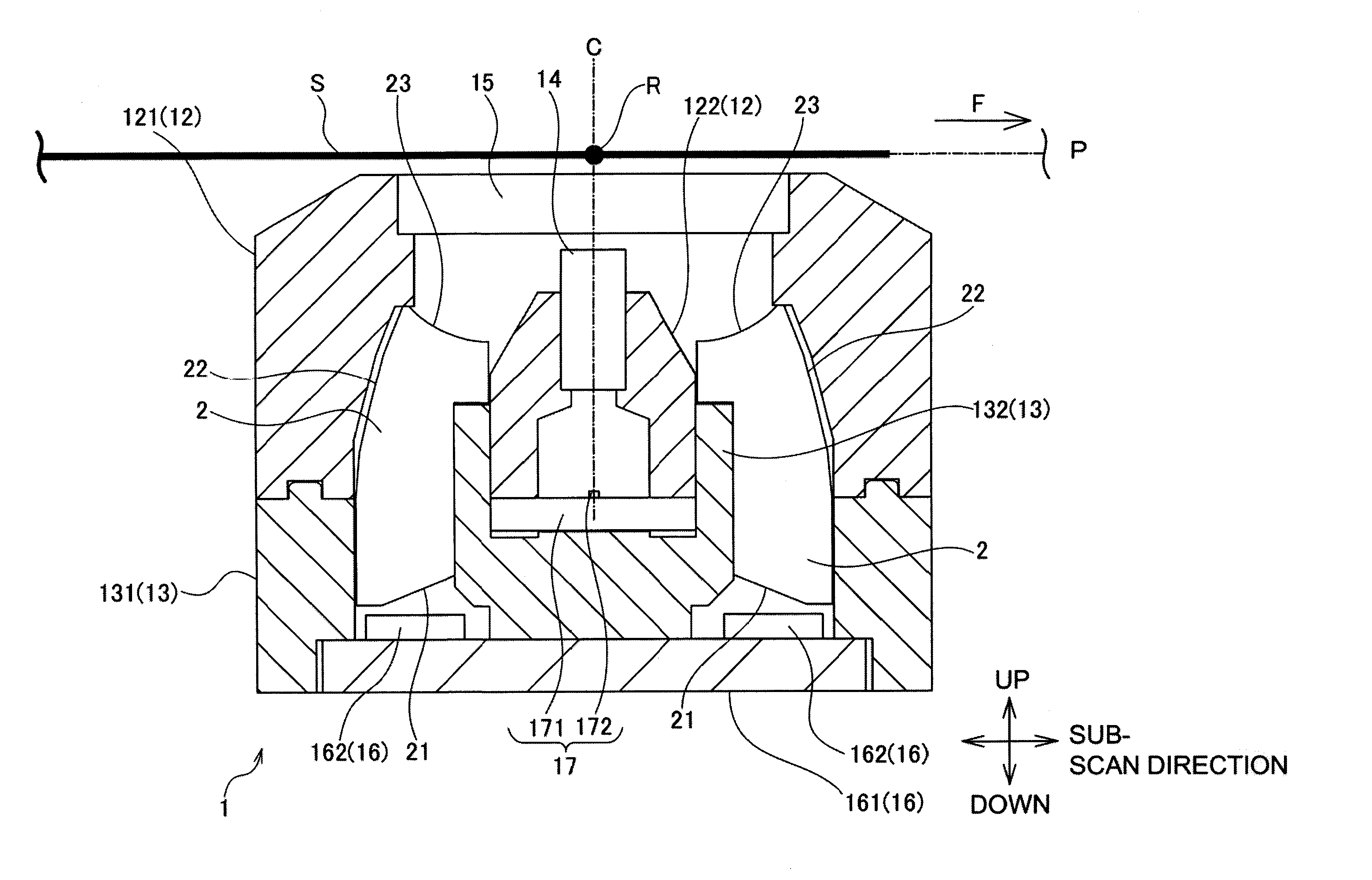
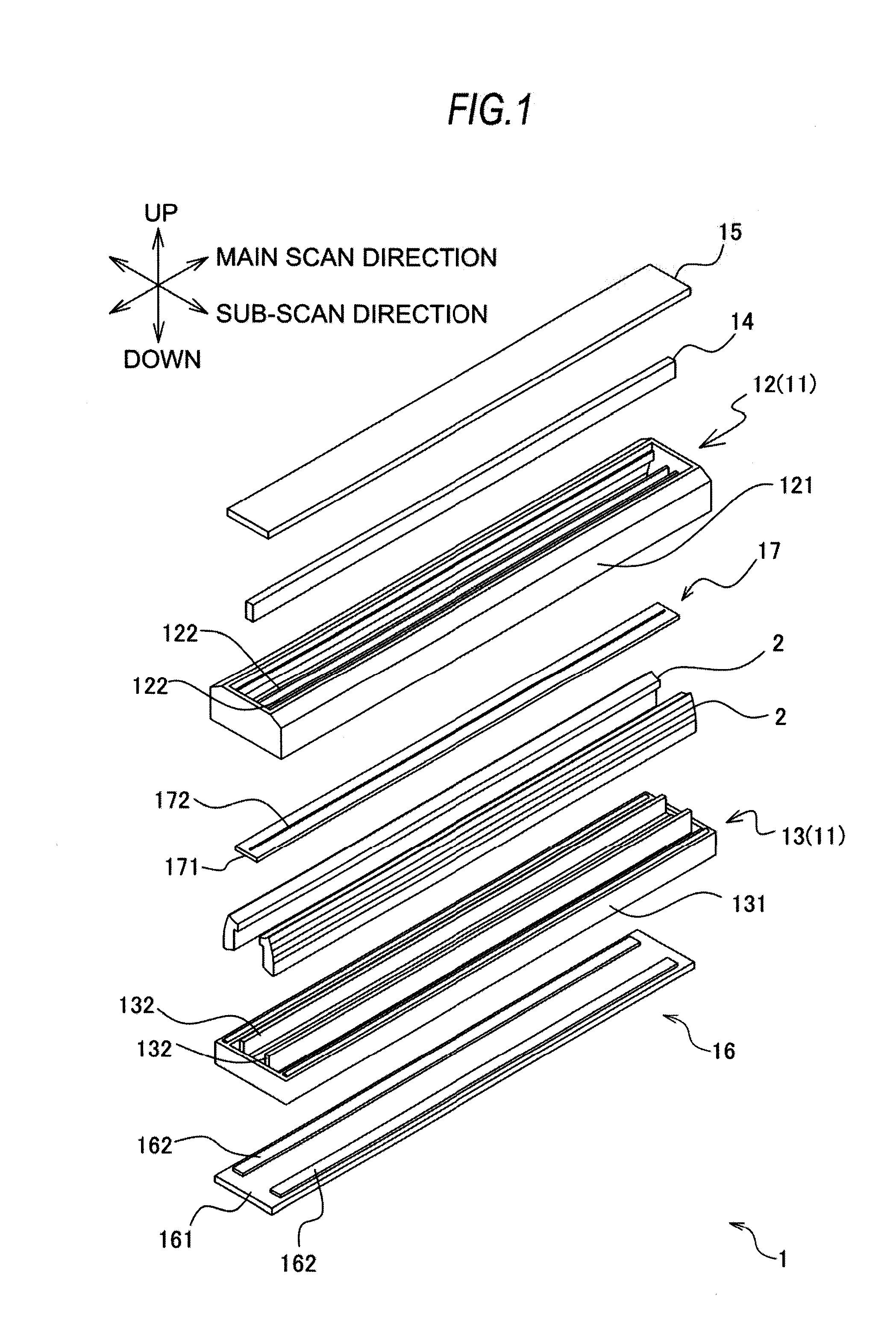
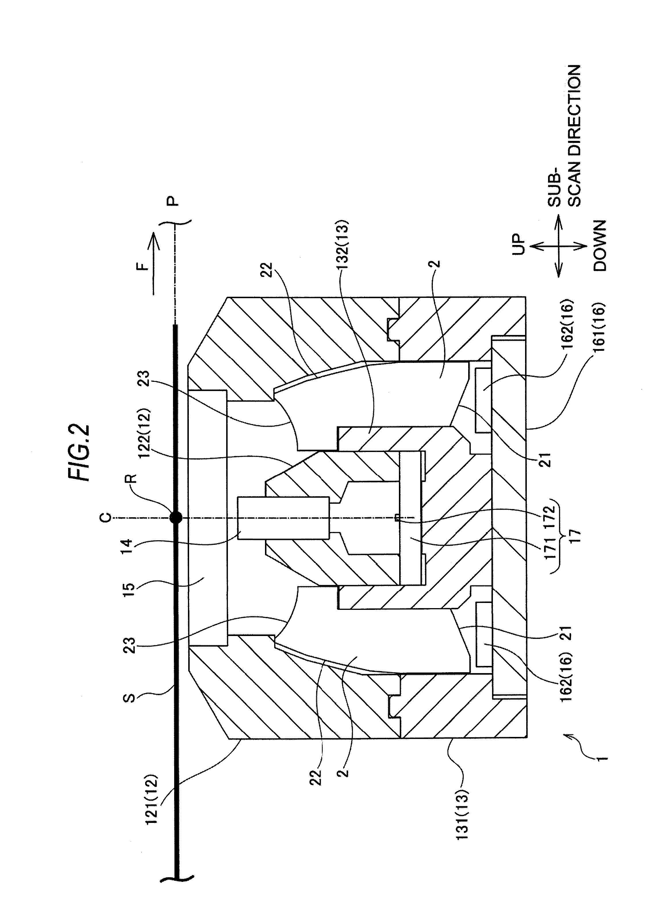
[0030]First, an overall configuration of an image sensor unit 1 according to the embodiment of the present invention will be described with reference to FIGS. 1 and 2. FIG. 1 is a schematic exploded perspective view showing a configuration of the image sensor unit 1. FIG. 2 is a schematic sectional view showing the configuration of the image sensor unit 1. In the drawings, the arrow F indicates a conveyance direction of a bill S, which is an object to be illuminated. In the drawings, alternate long and short dashed line P indicates a conveyance path of the bill S. For convenience of explanation, a part of the image sensor unit 1 over which the bill S passes will be referred to as an upper part of the image sensor unit 1, and the part opposite to the upper part will be referred to as a lower part. As shown in FIGS. 1 and 2, the image sensor unit 1 comprises a ligh...


PUM


Abstract

An image sensor unit has a light emitting module and a light guide that guides light emitted by the light emitting module to a bill, the light guide has an incident surface on which the light emitted by the light emitting module is incident, a reflection surface that reflects the light having entered the light guide through the incident surface, and an emission surface from which the light reflected by the reflection surface is emitted toward the bill, and the reflection surface is formed by a plurality of contiguous flat surfaces.

Description

CROSS-REFERENCE TO RELATED APPLICATIONS[0001]This application is based upon and claims the benefit of priority of the prior Japanese Patent Application No. 2011-174403, filed on Aug. 9, 2011, and the Japanese Patent Application No. 2012-163536, filed on Jul. 24, 2012, the entire contents of which are incorporated herein by reference.BACKGROUND OF THE INVENTION[0002]1. Field of the Invention[0003]The present invention relates to an image sensor unit used in an image reading apparatus, such as a copying machine, image scanner, facsimile and so on, and the image reading apparatus using the image sensor unit. In particular, it relates to an image sensor unit that reads image information from a recording medium, such as a bill, security and so on, and an image reading apparatus that authenticates the recording medium.[0004]2. Description of the Related Art[0005]For example, Japanese Laid-open Patent Publication No. 2007-116590 discloses an image reading apparatus that handles a bill.[000...

Claims


Application Information

Patent Timeline
Patent Type & Authority Applications(United States)
IPC IPC(8): H04N1/04
CPCH04N1/0285H04N1/02865H04N1/02855
Inventor YOSHIDA, HIDEMASAHORIGUCHI, TOMOYUKIFUJIWARA, AKIFUMITAKAHASHI, HIDEHISASHIMODA, SHUUICHI
Owner CANON COMPONENTS INC
Why Eureka
Try Eureka