Integral module power conditioning system

a power conditioning system and integrated module technology, applied in the direction of thermal-pv hybrid energy generation, solar thermal energy generation, sustainable buildings, etc., can solve the problems of additional components for installation, failure to allow the frame to be energized, and require a substantial level of effort to install mounting brackets and grounding wires

Inactive Publication Date: 2013-02-14
MARICI HLDG THE NETHERLANDS BV
View PDF7 Cites 51 Cited by
  • Summary
  • Abstract
  • Description
  • Claims
  • Application Information

AI Technical Summary

Problems solved by technology

A failure in the insulating material of the PV laminate could allow the frame to be energized up to 600 V dc.
These processes require additional components for installation and require a substantial level of effort to install mounting brackets and grounding wires.
Ground fault interruption (GFI) cannot prevent shock in this situation.
Much of the cost associated with installation of PV modules is the expense of an on-site electrician.

Method used


Image

  • Integral module power conditioning system
  • Integral module power conditioning system
  • Integral module power conditioning system

Examples


Embodiment Construction

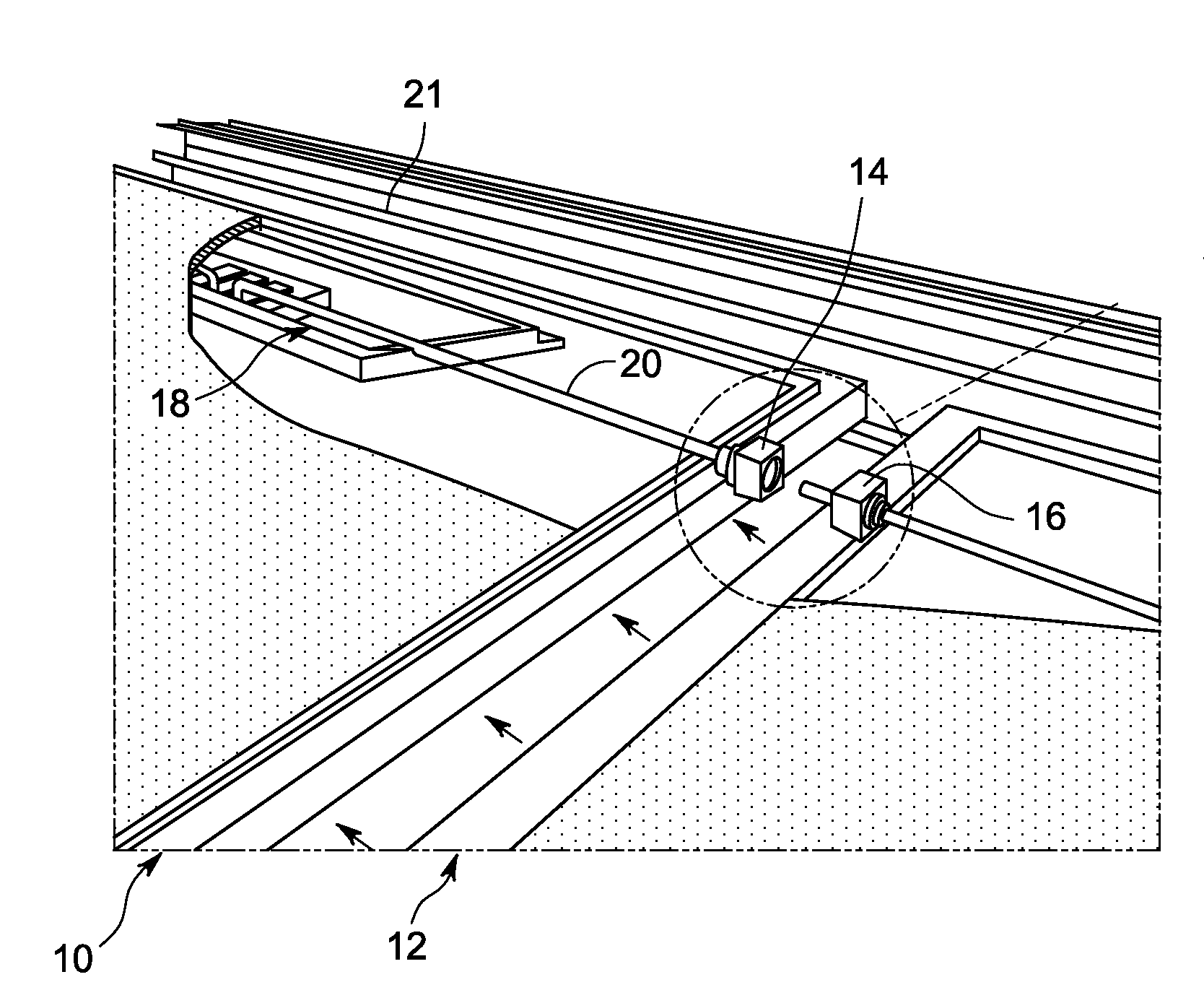
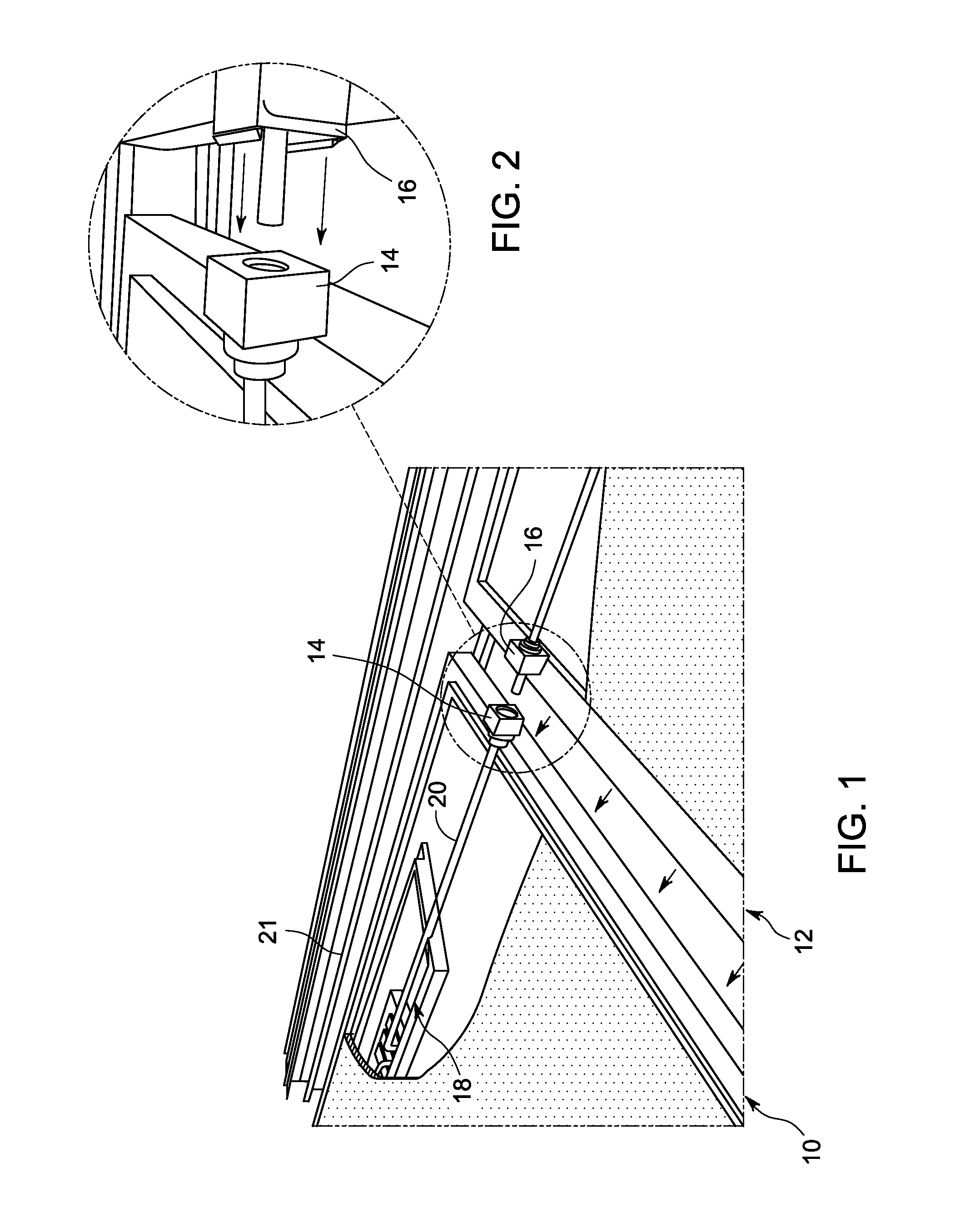
[0027]FIG. 1 illustrates a pair of solar module support frames 10, 12 with plug-and-play electrical connectors 14, 16 molded therein according to one embodiment. FIG. 2 depicts the electrical connectors 14, 16 in more detail. Electrical connector 14 can be seen to be a female electrical connector, while electrical connector 16 can be seen to be a male electrical connector. According to one aspect, plug-and-play electrical connectors 14, 16 comprise quick-connect type electrical jacks that are molded into their respective solar module support frames 10, 12. Each solar module support frame 10, 12 can accommodate a solar electrical module or a solar thermal module, described in more detail herein.

[0028]Plug-and-play, as used herein, is used to describe devices that work with a system as soon as they are connected. The user does not have to manually install drivers for the device or even tell the system that a new device has been added. Instead the system automatically recognizes the de...


PUM


Abstract

An integral solar module power conditioning system includes one or more solar module support frames. Each frame includes a plurality of plug-and-play electrical connectors integrated therewith. A microinverter or microinverter connector is also integrated with each frame. Each frame is configured to receive a respective solar electric module and to carry electrical power through a plurality of solar electric modules and corresponding microinverters connected together via a plurality of solar module support frames connected together via the plurality of integrated plug-and-play electrical connectors.

Description

BACKGROUND[0001]The subject matter of this disclosure relates generally to photovoltaic (PV) systems and more particularly to a system and method of integrating solar modules, inverters and frames into a common rack structure.[0002]Nearly all electrical systems in the U.S. are grounded to mitigate the impacts of lightning, line surges, or unintentional contact with high voltage lines. Most PV systems include modules with metal frames and metal mounting racks that are in exposed locations, e.g. rooftops, where they are subject to lightning strikes, or are located near high voltage transmission lines that in the event of high winds, etc., can come into contact with PV arrays.[0003]The modules in a typical PV array have aluminum frames that are often anodized. The 2008 National Electrical Code (NEC) that has the same requirements as the draft 2010-NEC and governs installation of PV systems requires exposed metal surfaces be grounded. There are special dc wiring and grounding requiremen...

Claims


Application Information

Patent Timeline
Patent Type & Authority Applications(United States)
IPC IPC(8): H02B1/01
CPCH01L31/02013H02S40/36H01L31/0521Y02E10/50Y02B10/20Y02B10/12Y02B10/70Y02E10/60F24J2/4647Y02E10/40H01L31/04H01L31/042H01L31/052H02S30/10H02S40/32H02S40/44H01L31/05F24S80/30Y02B10/10
Inventor KORMAN, CHARLES STEVENJOHNSON, NEIL ANTHONYDE ROOIJ, MICHAEL ANDREW
Owner MARICI HLDG THE NETHERLANDS BV
Why Eureka
Try Eureka