
Extension of physical downlink control channels in a communication system

a communication system and control channel technology, applied in the field of wireless communication systems, can solve the problems of limited dl control capacity, inability to expand control regions, and inability to achieve interference co-ordination in the frequency domain

Active Publication Date: 2013-02-14
SAMSUNG ELECTRONICS CO LTD
View PDF25 Cites 86 Cited by
  • Summary
  • Abstract
  • Description
  • Claims
  • Application Information

AI Technical Summary

Benefits of technology

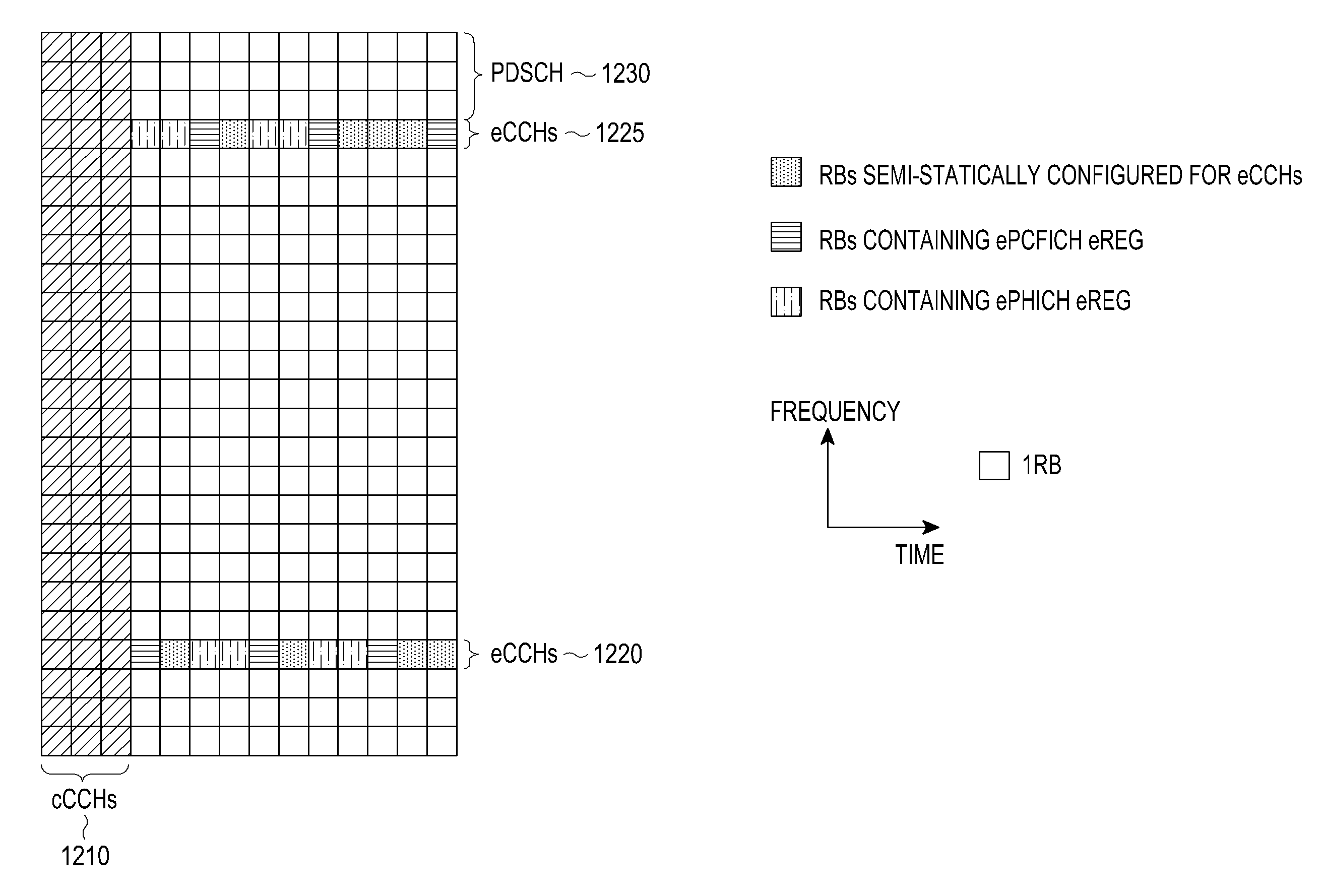
The present invention provides a method and apparatus for transmitting and receiving eCCHs, as well as a method for designing a transmission of a RS for demodulating eCCHs, a method for designing an operation for an ePCFICH and its multiplexing, transmission, and reception, and a method for transmitting a PDCCH to a UE over a TTI including a number of transmission symbols. The technical effects include improved transmission and reception of control signals and reference signals, as well as more efficient design of frequency RBs and transmission symbols for transmitting PDCCH.

Problems solved by technology

A UE is normally informed of NRBDL prior to a cPHICH reception, but this may not be possible for the total number of UL RBs, NRBUL, in an UL BW.
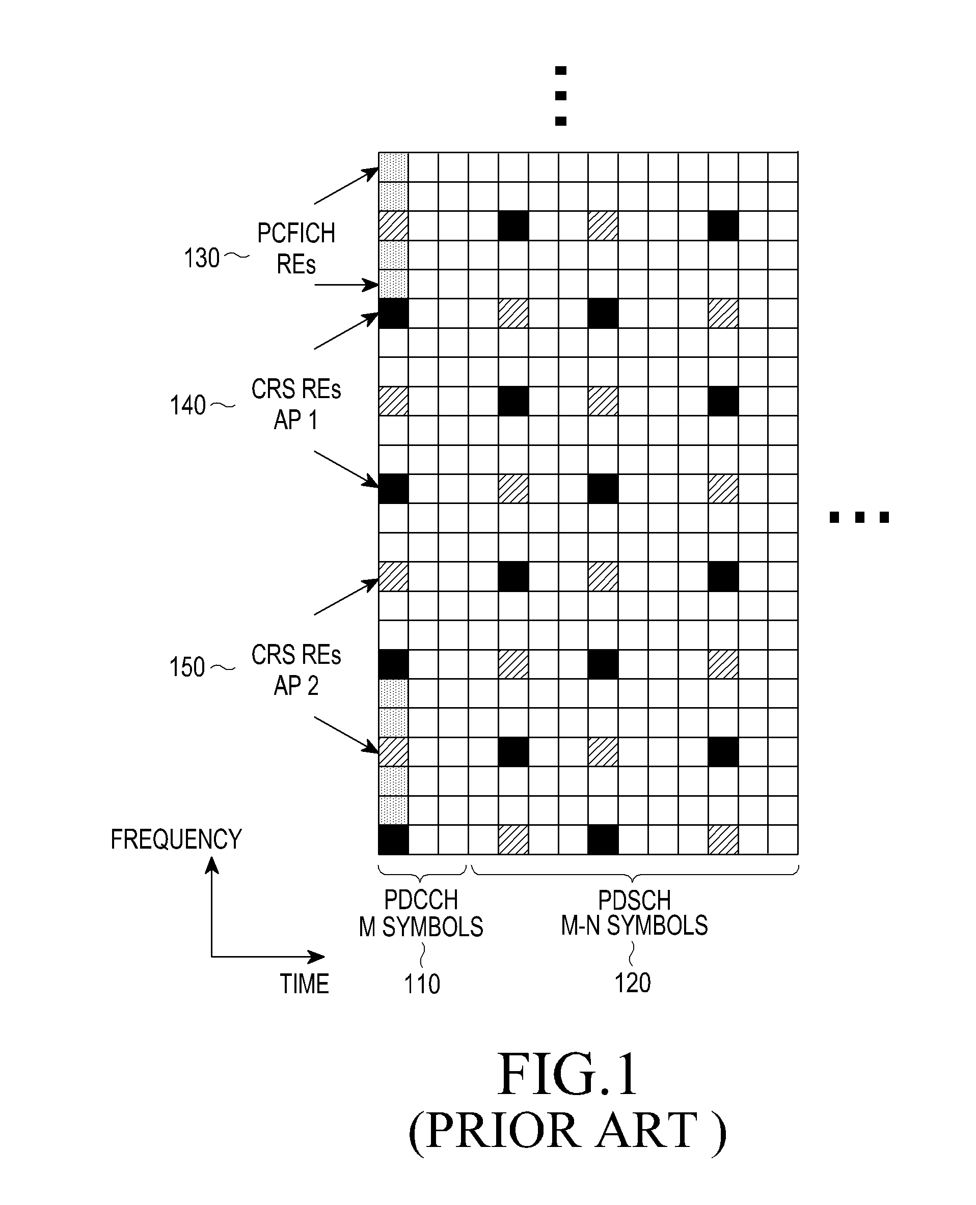
Consequently, the DL control has limited capacity and cannot achieve interference co-ordination in the frequency domain.
However, due to the cREG-based transmission and interleaving of the cCCHs, a conventional DL control region cannot be expanded to include more OFDM symbols while maintaining compatible operation with existing UEs, which will not be aware of such expansion.
Therefore, the CRS may not be generally relied upon for demodulating eCCHs.

Method used


Image

  • Extension of physical downlink control channels in a communication system
  • Extension of physical downlink control channels in a communication system
  • Extension of physical downlink control channels in a communication system

Examples


Embodiment Construction

[0090]Various embodiments of the present invention will now be described more fully hereinafter with reference to the accompanying drawings. This present invention may, however, be embodied in many different forms and should not be construed as limited to the embodiments set forth herein. Rather, these embodiments are provided so that this disclosure will be thorough and complete and will fully convey the scope of the present invention to those skilled in the art.

[0091]Additionally, although the embodiments of the present invention will be described below with reference to Orthogonal Frequency Division Multiplexing (OFDM), they also are applicable to all Frequency Division Multiplexing (FDM) transmissions in general and to Discrete Fourier Transform (DFT)-spread OFDM in particular.

[0092]In accordance with an embodiment of the present invention, aspects for an eCCH design include:[0093]a) A unit for an eCCH transmission is an eREG.[0094]b) An ePDCCH transmission includes at least one...


PUM


Abstract

Methods and apparatuses are described for a User Equipment (UE) to receive enhanced Control CHannels (eCCHs), including enhanced Physical Downlink Control CHannels (ePDCCHs), transmitted in a set of Resource Blocks (RBs) over a Transmission Time Interval (TTI). A method includes transmitting a first control signal to a first UE over a first number of Resource Elements (Res) in a subset of the RBs and over a first number of the transmission symbols in the TTI; transmitting a second control signal to a second UE over a second number of the REs in the subset of the RBs and over a second number of the transmission symbols in the TTI; and transmitting a reference signal of the first type over a third number of the REs in the subset of the RBs and over a third number of the transmission symbols in the TTI.

Description

PRIORITY[0001]The present application claims priority under 35 U.S.C. §119(e) to U.S. Provisional Application No. 61 / 522,399, which was filed in the United States Patent and Trademark Office on Aug. 11, 2011, the entire disclosure of which is incorporated herein by reference.BACKGROUND OF THE INVENTION[0002]1. Field of the Invention[0003]The present invention relates generally to wireless communication systems, and more particularly, to transmitting physical downlink control channels.[0004]2. Description of the Art[0005]A communication system includes a DownLink (DL) that conveys transmission signals from transmission points such as Base Stations (BSs) (or NodeBs) to User Equipments (UEs), and an UpLink (UL) that conveys transmission signals from UEs to reception points such as NodeBs. A UE, which is also commonly referred to as a terminal or a Mobile Station (MS), may be fixed or mobile and may be a cellular phone, a personal computer device, etc. A NodeB is generally a fixed stati...

Claims


Application Information

Patent Timeline
Patent Type & Authority Applications(United States)
IPC IPC(8): H04W72/04
CPCH04L1/0073H04L1/08H04L1/1893H04L1/0039H04L5/0055H04L5/0023H04L5/0048H04L5/0094H04L5/001H04L27/26
Inventor PAPASAKELLARIOU, ARISKIM, YOUNG-BUMZHANG, JIANZHONG
Owner SAMSUNG ELECTRONICS CO LTD
Learn More