
Coding of a spatial sampling of a two-dimensional information signal using sub-division

a two-dimensional information signal and sub-division technology, applied in signal generators with optical-mechanical scanning, color television with bandwidth reduction, etc., can solve the problem of large number of small blocks, the bit rate necessitated for transmitting the prediction parameters of the blocks can become significant, and the possibility of sub-dividing a picture (or a plane group) into blocks provided by the syntax is very limited

Active Publication Date: 2013-02-14
GE VIDEO COMPRESSION LLC
View PDF13 Cites 163 Cited by
  • Summary
  • Abstract
  • Description
  • Claims
  • Application Information

AI Technical Summary

Benefits of technology

The patent describes a way to make video or still pictures look better when they are encoded. The method works by making a trade-off between how complicated the data is and how well the video or picture looks. The result is that the method can make it look better while using less complicated data.

Problems solved by technology

In image and video coding standards, the possibilities for sub-dividing a picture (or a plane group) into blocks that are provided by the syntax are very limited.
The small set of possibilities for specifying the partitioning into blocks in state-of-the-art image and video coding standards has the advantage that the side information rate for signaling the sub-division information can be kept small, but it has the disadvantage that the bit rate necessitated for transmitting the prediction parameters for the blocks can become significant as explained in the following.
For arbitrarily shaped objects this can result in a large number of small blocks.
On the other hand, setting the coding parameters at a finer granularity poses a higher burden onto the amount of side information in order to inform the decoder on the settings.
Even further, it should be noted that any freedom for the encoder to (further) sub-divide the picture / video spatially into blocks tremendously increases the amount of possible coding parameter settings and thereby generally renders the search for the coding parameter setting leading to the best rate / distortion compromise even more difficult.
For example, if the maximum region size is high, the multi-tree sub-division information is likely to get more complex due to the treeroot regions getting larger.

Method used


Image

  • Coding of a spatial sampling of a two-dimensional information signal using sub-division
  • Coding of a spatial sampling of a two-dimensional information signal using sub-division
  • Coding of a spatial sampling of a two-dimensional information signal using sub-division

Examples


Embodiment Construction

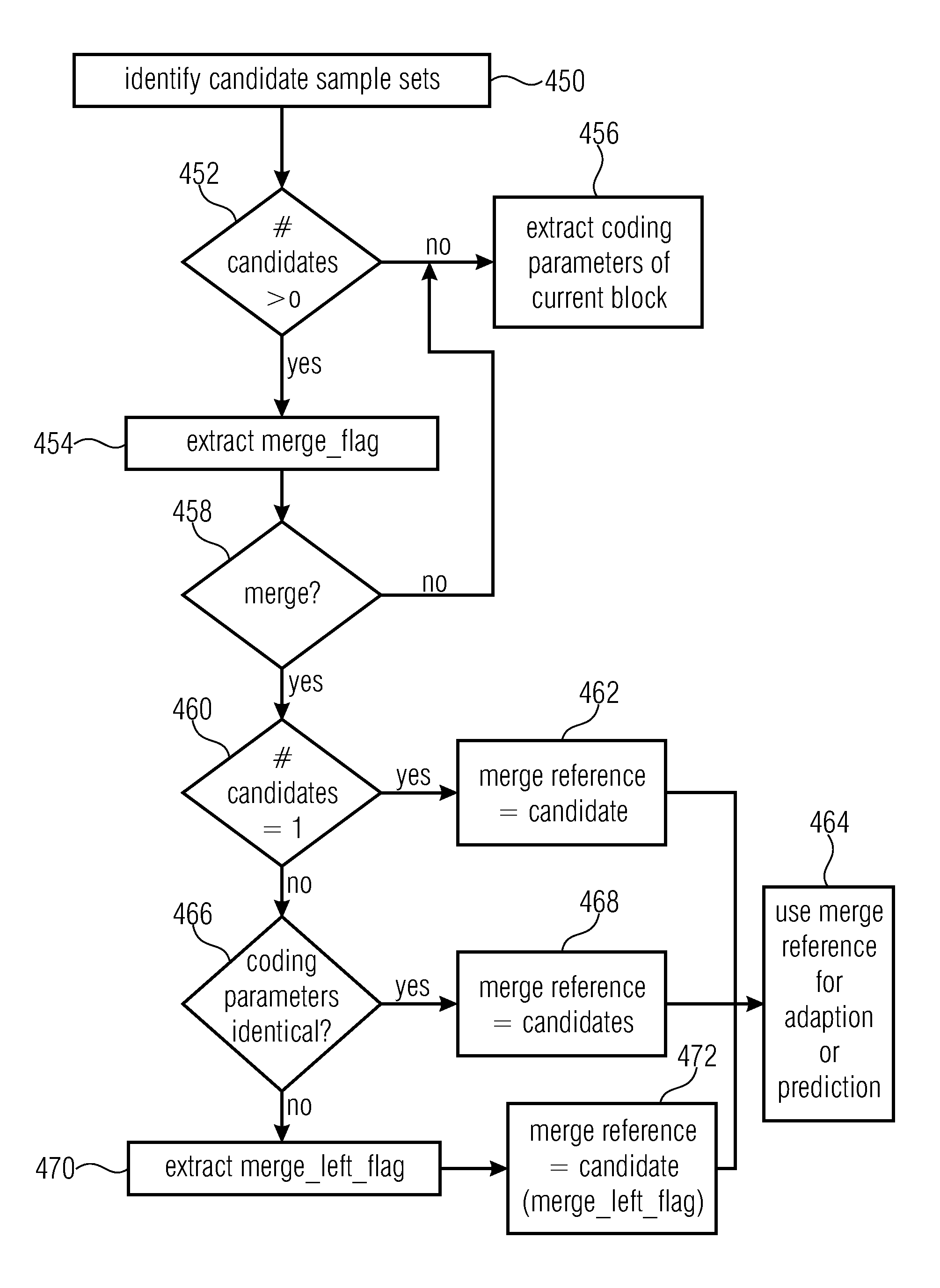
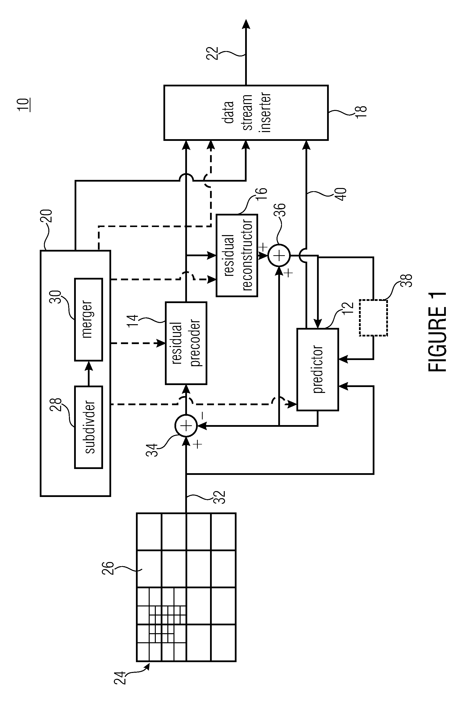
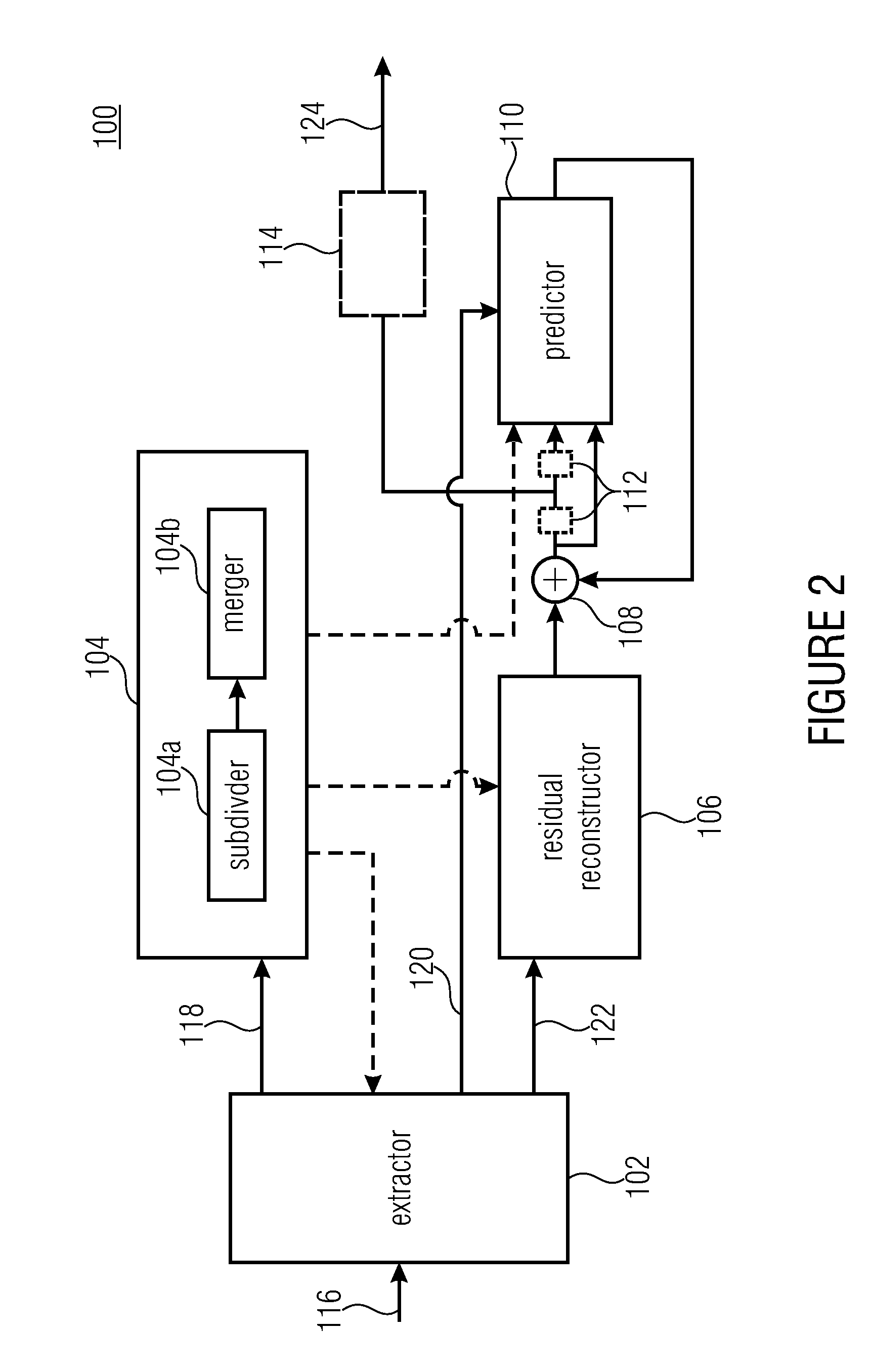
[0075]In the following description of the Figs., elements occurring in several of these Figs. are indicated by common reference numbers and a repeated explanation of these elements is avoided. Rather, explanations with respect to an element presented within one Fig. shall also apply to other Figs. in which the respective element occurs as long as the explanation presented with these other Figs. indicate deviations therefrom.

[0076]Further, the following description starts with embodiments of an encoder and decoder which are explained with respect to FIGS. 1 to 11. The embodiments described with respect to these Figs. combine many aspects of the present application which, however, would also be advantageous if implemented individually within a coding scheme and accordingly, with respect to the subsequent Figs., embodiments are briefly discussed which exploit just-mentioned aspects individually with each of these embodiments representing an abstraction of the embodiments described with...


PUM


Abstract

Coding schemes for coding a spatially sampled information signal using sub-division and coding schemes for coding a sub-division or a multitree structure are described, wherein representative embodiments relate to picture and / or video coding applications.

Description

CROSS-REFERENCE TO RELATED APPLICATIONS[0001]This application is a continuation of copending International Application No. PCT / EP2011 / 055534, filed Apr. 8, 2011, which is incorporated herein by reference in its entirety, and additionally claims priority from International Application No. PCT / EP2010 / 054843, filed Apr. 13, 2010 and European Patent Application No. EP 10159819.1, filed Apr. 13, 2010, all of which are incorporated herein by reference in their entirety.BACKGROUND OF THE INVENTION[0002]The present invention relates to coding schemes for coding a spatially sampled information signal using sub-division and coding schemes for coding a sub-division or a multitree structure, wherein representative embodiments relate to picture and / or video coding applications.[0003]In image and video coding, the pictures or particular sets of sample arrays for the pictures are usually decomposed into blocks, which are associated with particular coding parameters. The pictures usually consist of...

Claims


Application Information

Patent Timeline
IPC IPC(8): H04N7/32H04N7/26H04N19/593
CPCH04N19/52H04N19/53H04N19/96H04N19/46H04N19/91H04N19/119H04N19/176H04N19/70H04N19/13H04N19/186H04N19/30H04N19/17H04N19/59H04N19/593H04N19/1883H04N19/61
Inventor KIRCHHOFFER, HEINERWINKEN, MARTINHELLE, PHILIPPMARPE, DETLEVSCHWARZ, HEIKOWIEGAND, THOMAS
Owner GE VIDEO COMPRESSION LLC
Learn More