Carton feeder system and method for simultaneously feeding a plurality of cartons to a conveyor track using a plurality of pick-up heads

a carton feeder and conveyor track technology, applied in the field of carton feeders, can solve the problems not being able to achieve the effect of reducing the horizontal extension of the carton, not being able to solve the problem of not being able to reduce not being able to achieve the effect of reducing the cycle time for a specific operation, etc., to achieve the effect of reducing the horizontal extension

Active Publication Date: 2013-02-14
NORDEN MASCH AB
View PDF9 Cites 12 Cited by
  • Summary
  • Abstract
  • Description
  • Claims
  • Application Information

AI Technical Summary

Benefits of technology

[0013]By this first embodiment of the carton feeding system according to the invention, a carton feeding system is obtained that can insert cartons simultaneously into a continuously moving conveyor track having parallel teeth. This is achieved in that the cartons are held in a rhombic shape during the insertion and that the distance between the teeth corresponds to the erected carton, or in that the cartons are inserted in a rectangular shape and that the teeth comprises resilient elements. The rhombic shape of the cartons decreases the horizontal extension of the cartons during the insertion and provides some space between the cartons and the teeth. This space constitutes the tolerance that is needed to be able to insert a carton in a holding space with the same width as the carton itself. The insertion tolerance can also be obtained with the resilient means that allows rectangular cartons to be inserted into the conveyor track.
[0014]One advantage of being able to insert cartons when the teeth are parallel is that the cartons may be inserted on the straight conveyor track and not only at the infeed region at the end of the conveyor track. This in turn makes it possible to mount several mounting devices next to each other along the conveyor track. The mounting devices can then insert cartons simultaneously which allows for an increased insertion rate of the feeding system.
[0015]The rhombic shape of the carton is preferably such that the angle α, which is the angle between the upper wall and one of the side walls of the carton, is in the region between 50 and 80 degrees, and more preferably between 60 and 70 degrees. It is preferred to counterfold the cartons prior to the insertion, i.e. to open the cartons by more than 90 degrees, preferably in the region of between 100 to 140 degrees. This is of advantage since the carton will then be pretensioned towards a rectangular shape, instead of towards the original flat-folded shape. This in turn will make it easier to hold the erected carton in the conveyor track. A holding protrusion may be provided at one of the teeth in order to hold the carton in position. When the carton is inserted into the conveyor track, a hold down element may be used to stop the carton from escaping the conveyor track.
[0016]When the cartons are inserted in a rectangular shape, it is also of advantage to counterfold the cartons prior to the insertion. This will help the cartons to hold the rectangular shape during the insertion of objects into the carton at a later stage.

Problems solved by technology

Such a solution is often difficult to achieve since it may involve a redesign of the machine and at some point, it is not possible to reduce the cycle time for a specific operation.
Such a solution requires more space and is not as cost-effective, but may be a possibility when an older production line is to be upgrades.
These solutions may work well for some applications, but may be inflexible, especially when the throughput of the system is to be increased.

Method used


Image

  • Carton feeder system and method for simultaneously feeding a plurality of cartons to a conveyor track using a  plurality of pick-up heads
  • Carton feeder system and method for simultaneously feeding a plurality of cartons to a conveyor track using a  plurality of pick-up heads
  • Carton feeder system and method for simultaneously feeding a plurality of cartons to a conveyor track using a  plurality of pick-up heads

Examples


first embodiment

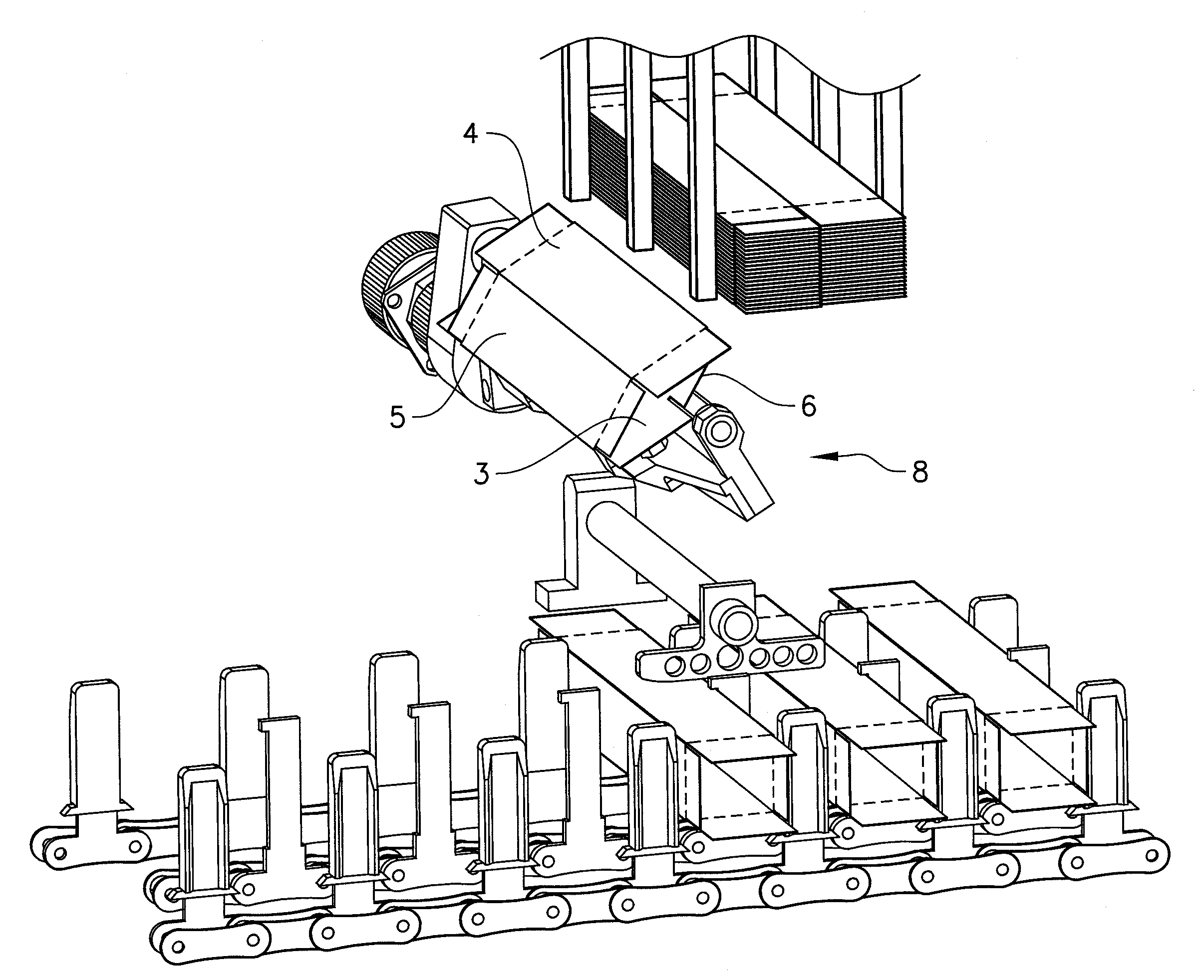
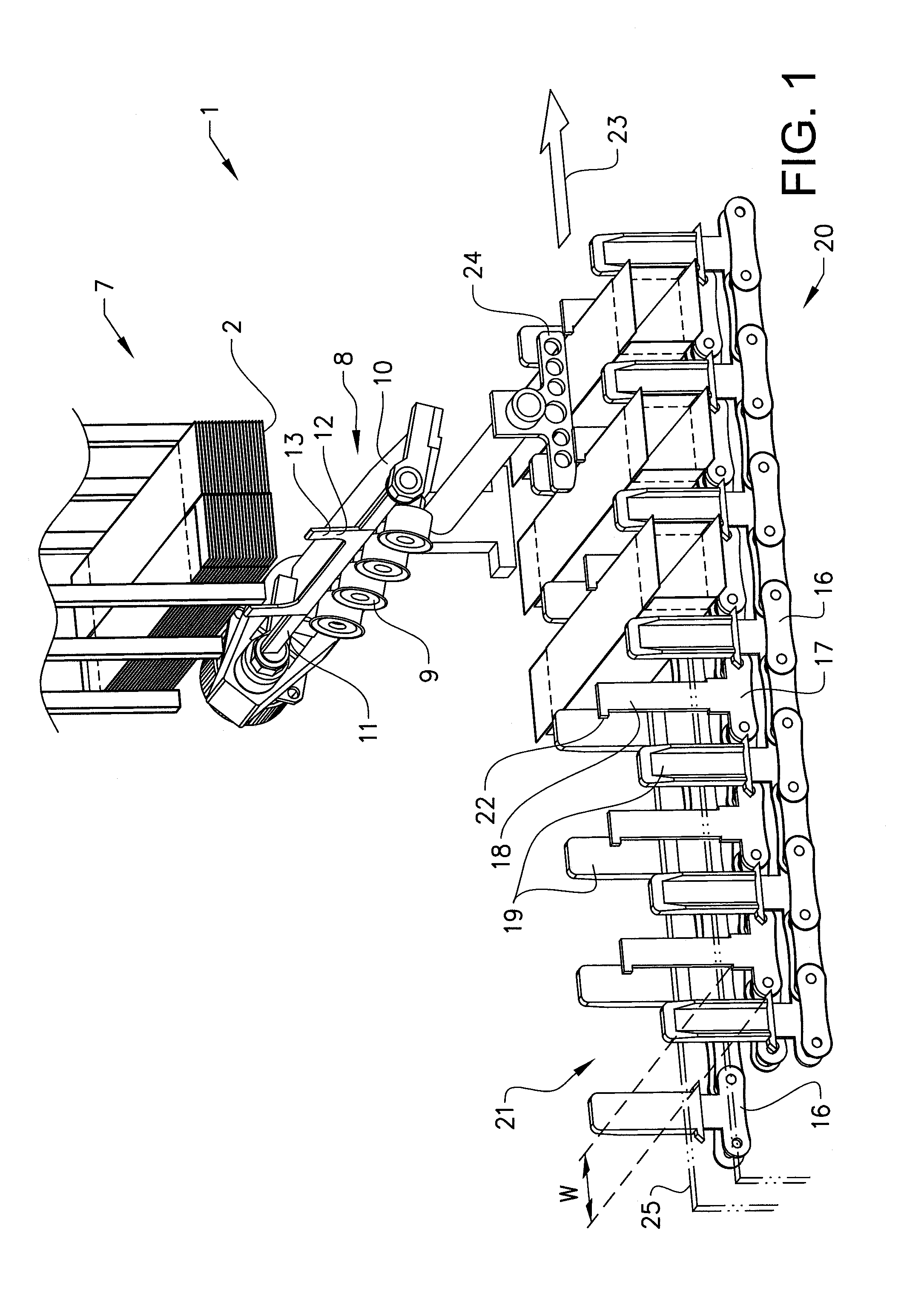
[0031]FIGS. 1 to 6 shows a carton feeding device 1 adapted to pick-up carton blanks 2 from a magazine, to open them and to subsequently feed them to a conveyor track. The carton blanks 2 are flat-folded, pre-glued cartons comprising four sides and having closure flaps at their end regions. When a carton blank is erected or opened, a rectangular box body is obtained, into which an object such as a tube or bottle is to be inserted, before the box is closed and / or sealed. The sides of the carton will in this description be referred to as the upper wall 3, the lower wall 4, the front wall 5 and the rear wall 6. These references indicate the directions of the sides of a carton being conveyed in the conveyor track, with reference to the moving direction of the conveyor track. The carton blanks 2 are fed from a magazine 7. The magazine is vertically disposed such that the carton blanks are removed downwards from the magazine. In FIG. 1, the magazine 7 is also shown. In the shown example, t...

second embodiment

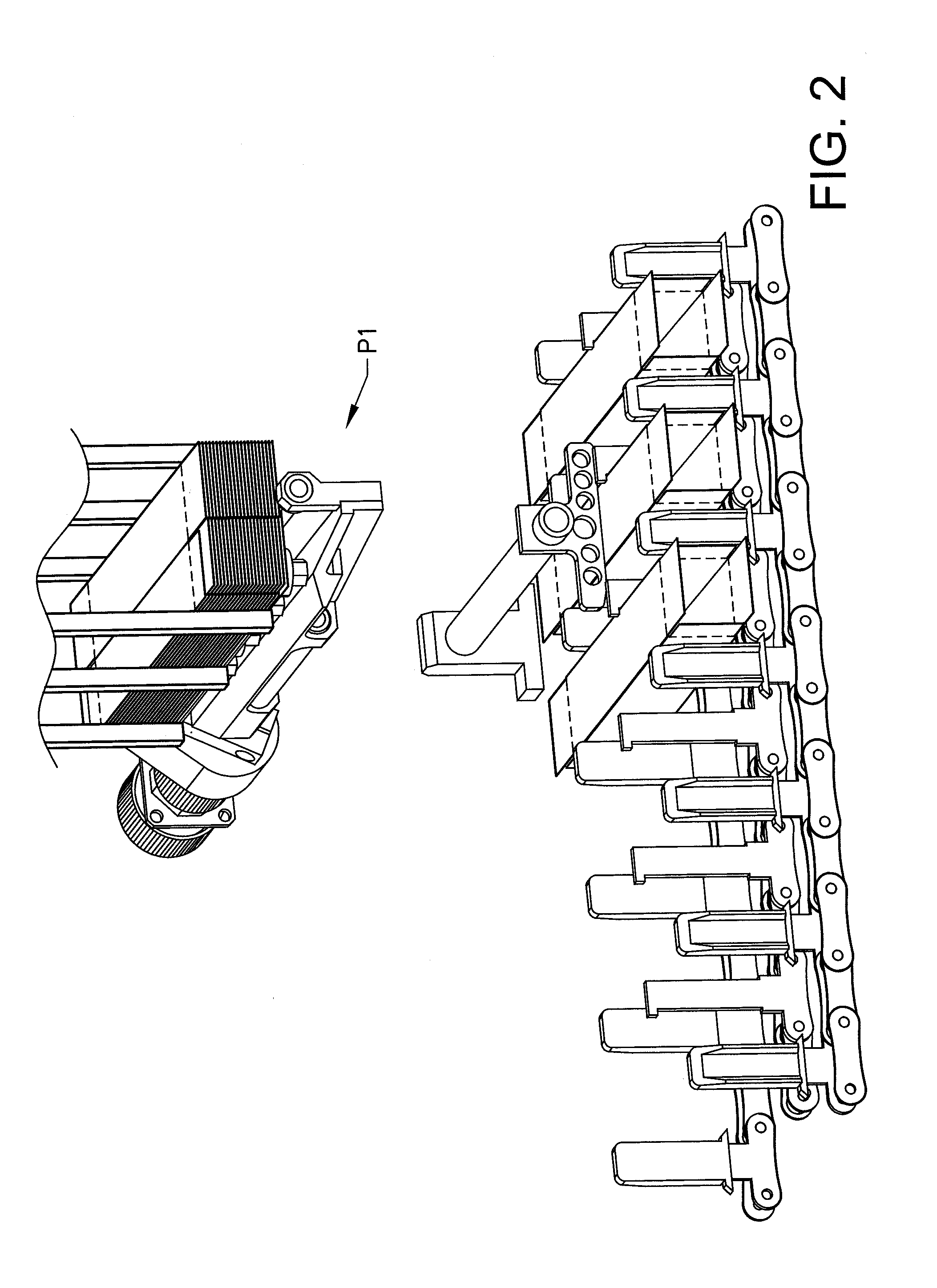
[0046]a carton feeding device 100 is shown in FIGS. 9 and 10. The pick-up head is in this example that same as pick-up head 8 as described above. In FIG. 9, the pick-up position P10 is shown. This pick-up position is the same as P1 described above.

[0047]FIG. 9 also shows a conveyor track 120 having protruding teeth extending from the surface of the conveyor track. In this example, the conveyor track comprises two conveyor chains, an outer conveyor chain 116 consisting of two chains that travel fixed to each other, and an inner chain 117 that travels together with the outer chain. The outer chain is provided with trailing teeth 119 that will support the rear walls of the carton through a resilient element 125. The resilient element 125 protrudes from the forward face of the tooth and may be designed in different ways. In the shown example, a bend blade spring constitutes the resilient element. Other types of springs are also possible to use, as well as resilient materials and also ri...


PUM

PropertyMeasurementUnit
angleaaaaaaaaaa
angleaaaaaaaaaa
angleaaaaaaaaaa

Abstract

Embodiments include a carton feeding system for feeding a plurality of cartons to a conveyor track, comprising a plurality of feeding devices, where each feeding device comprises a pick-up head with a plurality of vacuum cups, and an erecting finger pivotally suspended at the pick-up head, where the pick-up head has a pick-up position (P1) in which the holding plane of the pick-up head is positioned parallel to the folded carton blank that is to be picked up, and an insertion position (P2) in which the erecting finger is pivoted with respect to the holding plane of the pick-up head in such a way that the carton is opened, and where at least two cartons are inserted simultaneously into the conveyor track.

Description

TECHNICAL FIELD[0001]Carton feeder system and method for simultaneously feeding a plurality of cartons to a conveyor track using a plurality of pick-up heads.BACKGROUND ART[0002]In the industry concerned with packing smaller objects such as tubes, bottles and the like in carton boxes, there is a constant need to increase the productivity of the packing machines. One aspect of a packing machine is the number of units that the machine can handle during a specific time interval. There are different ways of achieving a higher throughput in such a machine. One way is to reduce the cycle time for each object, i.e. to allow more objects to pass the machine during the same time interval. Such a solution is often difficult to achieve since it may involve a redesign of the machine and at some point, it is not possible to reduce the cycle time for a specific operation. Another way to increase the throughput in a production line is to use several parallel machines, at least for some operations....

Claims


Application Information

Patent Timeline
Patent Type & Authority Applications(United States)
IPC IPC(8): B65G47/04
CPCB31B1/00B31B2201/027B31B2201/286B31B2203/082B65B43/265B65H2403/543B65B43/325B65H2301/42322B65H2405/36B65H3/0883B65B43/305B31B50/00B31B50/062B31B50/786B31B50/788B31B2100/0022B31B50/80B31B50/804B31B2100/00B31B2120/30
Inventor LUNDGREN, CHRISTERNILSSON, JAN
Owner NORDEN MASCH AB
Why Eureka
Try Eureka