Manual unlocking structure for power feeding plug locking device
- Summary
- Abstract
- Description
- Claims
- Application Information
AI Technical Summary
Benefits of technology
Problems solved by technology
Method used
Image

Examples
first embodiment
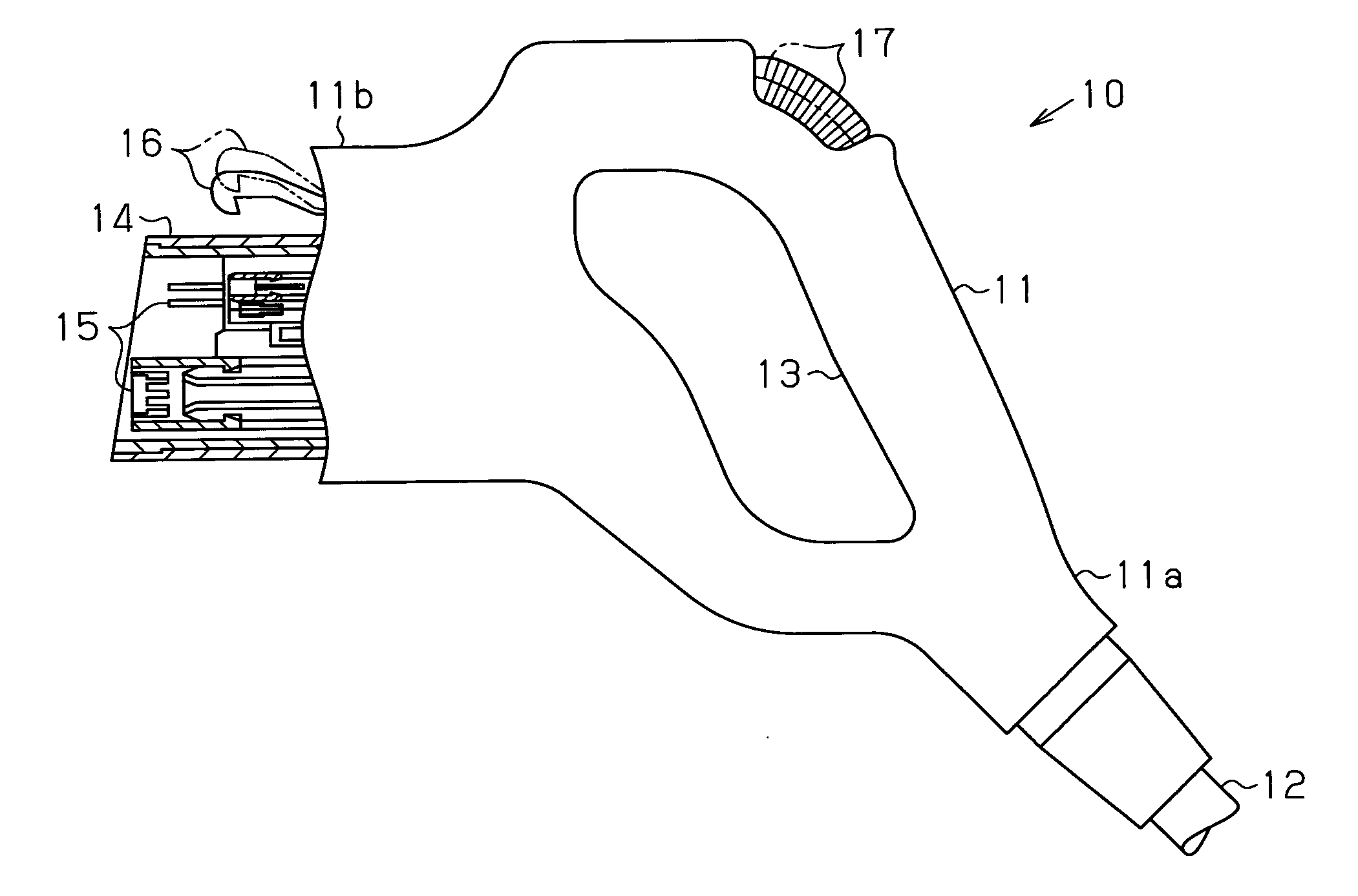
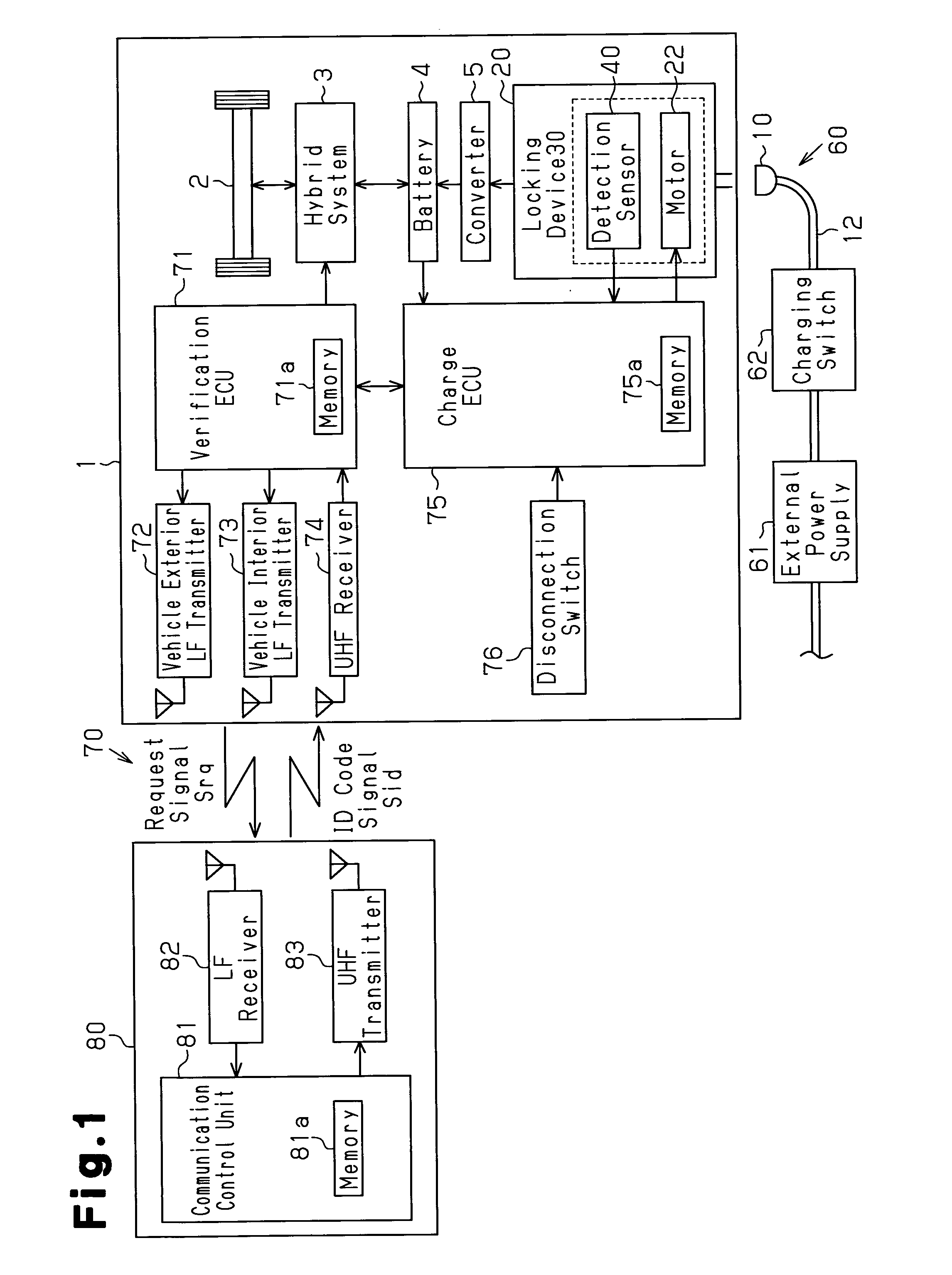
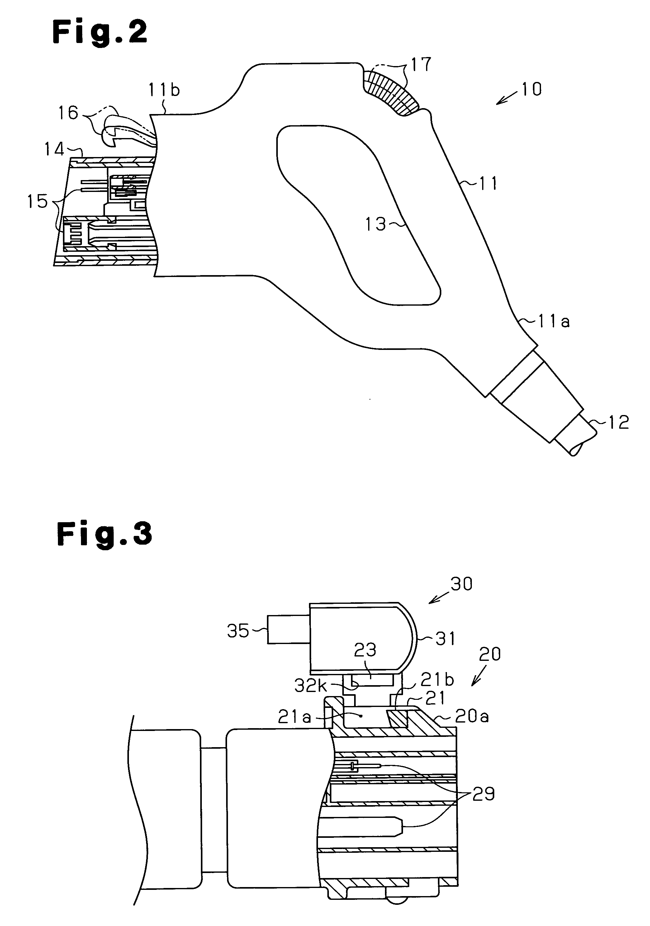
[0039]A manual unlocking structure for a power feeding plug locking device according to a first embodiment of the present invention applied to a power receiving connector of a plug-in hybrid vehicle will now be discussed with reference to FIGS. 1 to 10.
[0040]Referring to FIG. 1, a plug-in hybrid vehicle 1 includes drive wheels 2 and a hybrid system 3, which uses an engine and a motor in combination to drive the drive wheels 2. The hybrid system 3 operates in a mode using only the engine to drive the drive wheels 2, a mode using the motor to drive the drive wheels 2 while generating electric power with the engine, a mode using both the engine and the motor to drive the drive wheels 2, and a mode using only the motor to drive the drive wheels 2. One of these modes is selected to drive the vehicle 1.
[0041]The hybrid system 3 is connected to a battery 4, which supplies the motor with power. In addition to being charged by the power generated by the engine, the battery 4 is chargeable by...
second embodiment
[0100]A manual unlocking structure for a power feeding plug locking device according to a second embodiment of the present invention applied to a power receiving connector of a plug-in hybrid vehicle will now be discussed with reference to FIGS. 11 to 15. The description hereafter will center on differences from the first embodiment. The manual unlocking mechanism of the second embodiment is similar to that of the first embodiment.
[0101]The structure of the locking device 30 in the second embodiment will now be discussed.
[0102]A lock bar 43, which serves as a restriction member (in broad terms, a fastening member), is rod-shaped. The lock bar 43 includes a lock portion 43a and a shaft portion 43b. The lock portion 43a restricts movement of the hook 16, and the shaft portion 43b is coupled to the lock portion 43a. A spring 48, which serves as an urging member, is arranged on the shaft portion 43b. The shaft portion 43b has an outer diameter that is smaller than that of the lock porti...
third embodiment
[0118]A manual unlocking structure for a power feeding plug locking device according to a third embodiment of the present invention applied to a power receiving connector of a plug-in hybrid vehicle will now be discussed with reference to FIGS. 20 to 25. The third embodiment includes a locking device 90, which differs from the first embodiment. The description hereafter will center on differences from the first embodiment.
[0119]The structure of the locking device 90 in the second embodiment will now be discussed.
[0120]As shown in FIGS. 20 to 25, the locking device 90 includes a main body case 92, which forms a shell of the locking device 90. The main body case 92 is formed integrally with the upper part of an outer surface 20a of an inlet 20. The main body case 92 includes a catch 21. In the same manner as the first embodiment, the catch 21 includes a cavity 21a and a projection 21b, which is engageable with a hook 16.
[0121]An engagement member 91, which integrally includes the proj...
PUM
 Abstract
Description
Claims
Application Information
 - Generate Ideas
- Intellectual Property
- Life Sciences
- Materials
- Tech Scout
- Unparalleled Data Quality
- Higher Quality Content
- 60% Fewer Hallucinations
Browse by: Latest US Patents, China's latest patents, Technical Efficacy Thesaurus, Application Domain, Technology Topic, Popular Technical Reports.
© 2025 PatSnap. All rights reserved.Legal|Privacy policy|Modern Slavery Act Transparency Statement|Sitemap|About US| Contact US: help@patsnap.com