Hyper-aeration apparatus for attic ventilation

a ventilation apparatus and attic technology, applied in ventilation systems, lighting and heating apparatuses, heating types, etc., can solve the problems of inefficiency of ventilation methods, low efficiency of intake air performance, and large amount of heat transfer from exposed roof structures to air, so as to accelerate the approach to cooling the attic space, reduce the time to provide cooler air, and increase the net air volume. , the effect of increasing the turnover rate of fresh air

Active Publication Date: 2013-02-14
PAUL STUART & ASSOCS
View PDF7 Cites 34 Cited by
  • Summary
  • Abstract
  • Description
  • Claims
  • Application Information

AI Technical Summary

Benefits of technology

[0041]The present invention provides an accelerated approach to cooling the attic space by increasing the air volume delivered, net air volume, and fresh air turnover rates, thus improving and reducing the time to provide cooler air into the attic space. The present invention reduces heat gain forces, thermo storage, thermal heat mass, heat load and the thermo shock effect from solar radiation by delivering cooler air directly at the ceiling level not just at the underside of an attics roof interior.
[0042]The present invention can equalize, reduce, prevent or eliminate the negative pressure or vacuum effects caused by the prior art found in traditional power attic ventilators. The present invention by normalizing these pressures can reduce the actions of the removal of conditioned air from the building structure through ceiling leaks and bypasses. The present invention can reduce or prevent the pulling pollutants from the crawlspace such as mold, radon, and sewer gasses into the building structure. The present invention can decrease the chances of the back drafting of fireplaces, water heaters and other fuel-burning appliances.
[0043]The invention eliminates the rate on putting the concern for the entrainment of intake moisture during operation. The invention eliminates the use of roof mounted intake ventilators, mounted just before the overhang, located directly in a heat effective zone which can bring hot air into the attic space generated by the radiation absorbed by the roof shingles. The invention eliminates the ventilation challenge...

Problems solved by technology

For most end users located around and in between the earth's circle of latitude parallel planes 40 degrees north and 40 degrees south, air conditioning accounts for a substantial portion of the annual energy expense, Although most building structures are insulated, a substantial amount of energy is expended by the air conditioning compressor to pump the radiant absorbed by the building structure out of the air conditioned living space into the outside ambience.
The results are a large amount of heat is transferred from the exposed roof structure to the air trapped within the attic air space.
This type static ventilation technology meets the minimum in building ventilation requirements and is also minimally efficient in regards to in...

Method used


Image

  • Hyper-aeration apparatus for attic ventilation
  • Hyper-aeration apparatus for attic ventilation
  • Hyper-aeration apparatus for attic ventilation

Examples


Embodiment Construction

[0075]While the invention is susceptible to various modifications and alternate forms, specific embodiments thereof have been shown by way of example in the drawings and herein described in detail. It should be understood, however that the description herein of specific embodiments is not intended to limit the invention to the particular forms disclosed. It is also to be understood that there is no invention to limit the invention to the specially disclosed embodiments but that the invention may be practiced using other features, elements methods and embodiments.

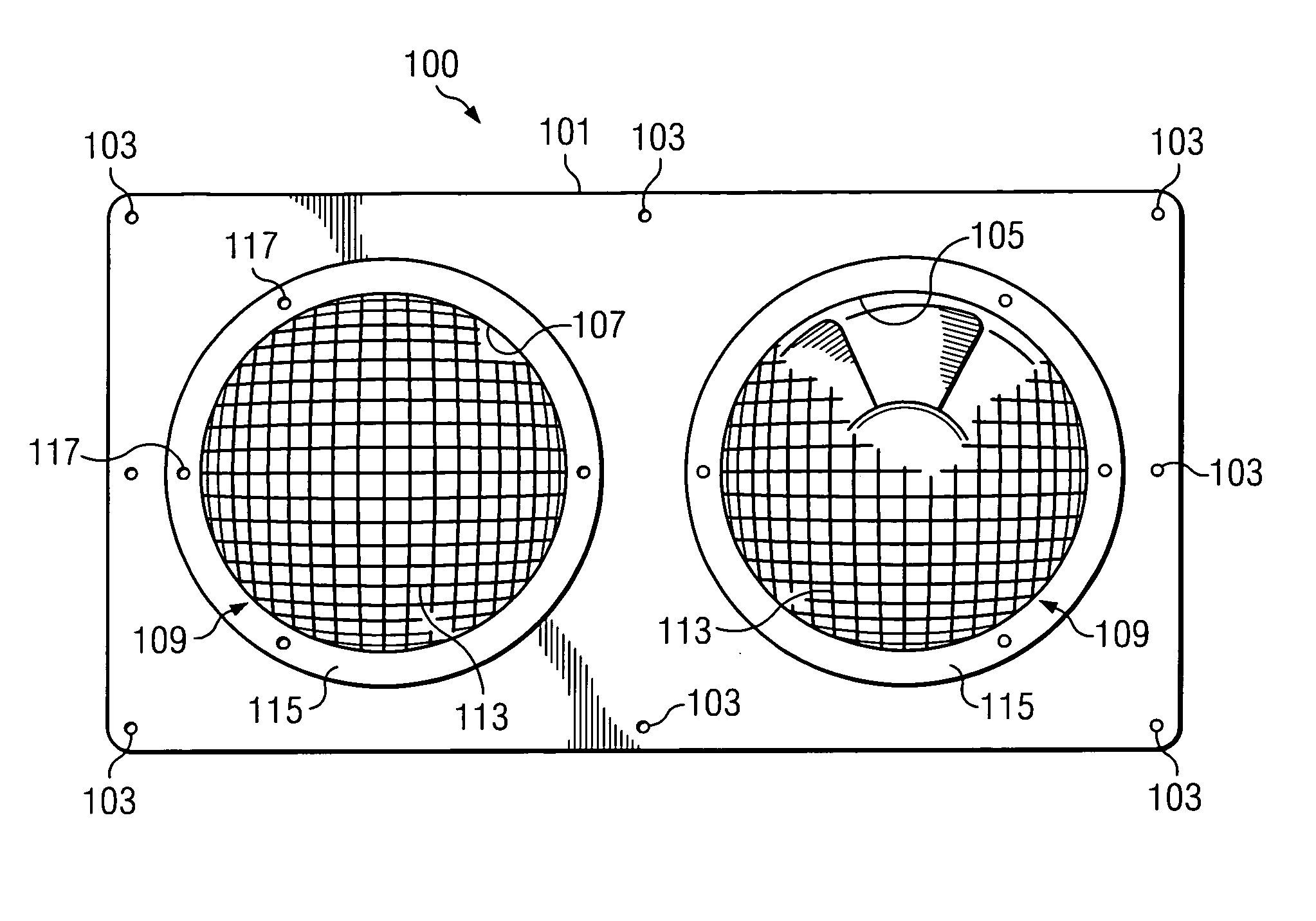
[0076]FIG. 1 illustrates a bottom view of the aeration apparatus (100) (or novel soffit vent) of the present invention, and the aeration apparatus (100) may include a mounting platform / plate 101 which may be formed from a solid aluminum, stainless or metal plate, wood, plastic or other suitable material. The mounting plate 101 may be rigid and formed in a rectangle, square, oval, circle or other shape device and may be shape...


PUM


Abstract

An aeration/ventilation device to be mounted on an aperture of a soffit may include a mounting platform to cooperate with the aperture of the soffit, a motor housing connected to the mounting platform, and a fan motor connected to the motor housing to a.) pull/draw cooler air in from the exterior of the soffit (under-eave) area of the building structure thus forcing the cooler air into the soffit interior and on into the attic space. b.) pull/draw hotter air out from the attic space into the interior of the soffit area thus forcing the hotter air out from the under-eave area of the structure. The aeration/ventilation device my use a double, single or multiple fan motors. These fan motors may be fixed to or be adjustable to the pitch angle of the roof structures. The aeration device my also include an electronic control housing to control the operation of the fan motors. The exhaust side of the motors may be fitted with adjustable air thruster device to create the effective exhaust velocity for improved air ventilation and circulation, along with a domed intake screens designed for improved air intake velocity. As well as being equipped with an intake rain guard(s).

Description

CROSS-REFERENCE TO RELATED APPLICATIONS[0001]N / A.STATEMENT REGARDING FEDERALLY SPONSORED RESEARCH OR DEVELOPMENT[0002]N / AREFERENCE TO MICROFICHE APPENDIX[0003]N / ABACKGROUND OF THE INVENTION[0004]1. Field of the Invention[0005]This invention relates generally to the art and science of ventilating building structures, and in particular to an apparatus that provides an attic aeration / ventilation method by powering, forcing, pushing or drawing cooler air into the attic space from the soffit or under-eave area location / region of a building structure.[0006]2. Description of the Related Art[0007]Because of climate changes related to global warming and the continued rapid demand and rising cost of energy, along with the incentives to preserve our energy resources, conservation is paramount for both domestic and the industrial / commercial end user.[0008]For most end users located around and in between the earth's circle of latitude parallel planes 40 degrees north and 40 degrees south, air co...

Claims


Application Information

Patent Timeline
IPC IPC(8): F24F7/007
CPCF24F7/025
Inventor POTTER, PAUL S.
Owner PAUL STUART & ASSOCS
Why Eureka
Try Eureka