Mechanical locking system for floor panels

a technology of locking system and floor panel, which is applied in the direction of floors, building components, floors, etc., can solve the problems of complicated snap connection, large cost of injection moulding tongue, and large cost of whole tongue blank 50/b>, so as to achieve cost-efficient and optimise cost and function

Active Publication Date: 2013-02-21
CERALOC INNOVATION AB
View PDF11 Cites 160 Cited by
  • Summary
  • Abstract
  • Description
  • Claims
  • Application Information

AI Technical Summary

Benefits of technology

[0023]An overall objective of embodiments of the present disclosure is to provide an improved and more cost efficient locking system for primarily rectangular floor panels with long and short edges installed in parallel rows, which allows that the short edges may be locked to each o

Problems solved by technology

Such a snap connection is complicated since a hammer and a tapping block usually needs to be used to overcome the friction between the long edges and to bend the strip during the snapping action.
One disadvantage is that the whole tongue blank 50 is made of a high quality plastic material that is rather costly.
A second disadvantage is that each tongue blank 50 must be individually designed for a specific width of a floor panel and this requires a wide range of expensive injection moulding tongues for each width.
A third disadvantage is that glass f

Method used


Image

  • Mechanical locking system for floor panels
  • Mechanical locking system for floor panels
  • Mechanical locking system for floor panels

Examples


Embodiment Construction

[0058]To facilitate understanding, several locking systems in the figures are shown schematically. It should be emphasised that improved or different functions may be achieved using combinations of the embodiments.

[0059]All embodiments may be used separately or in combinations. Angles, dimensions, rounded parts, spaces between surfaces etc. are only examples and may be adjusted within the basic principles of the disclosure.

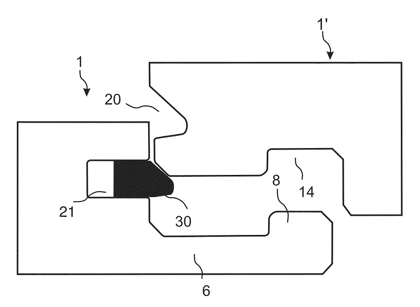
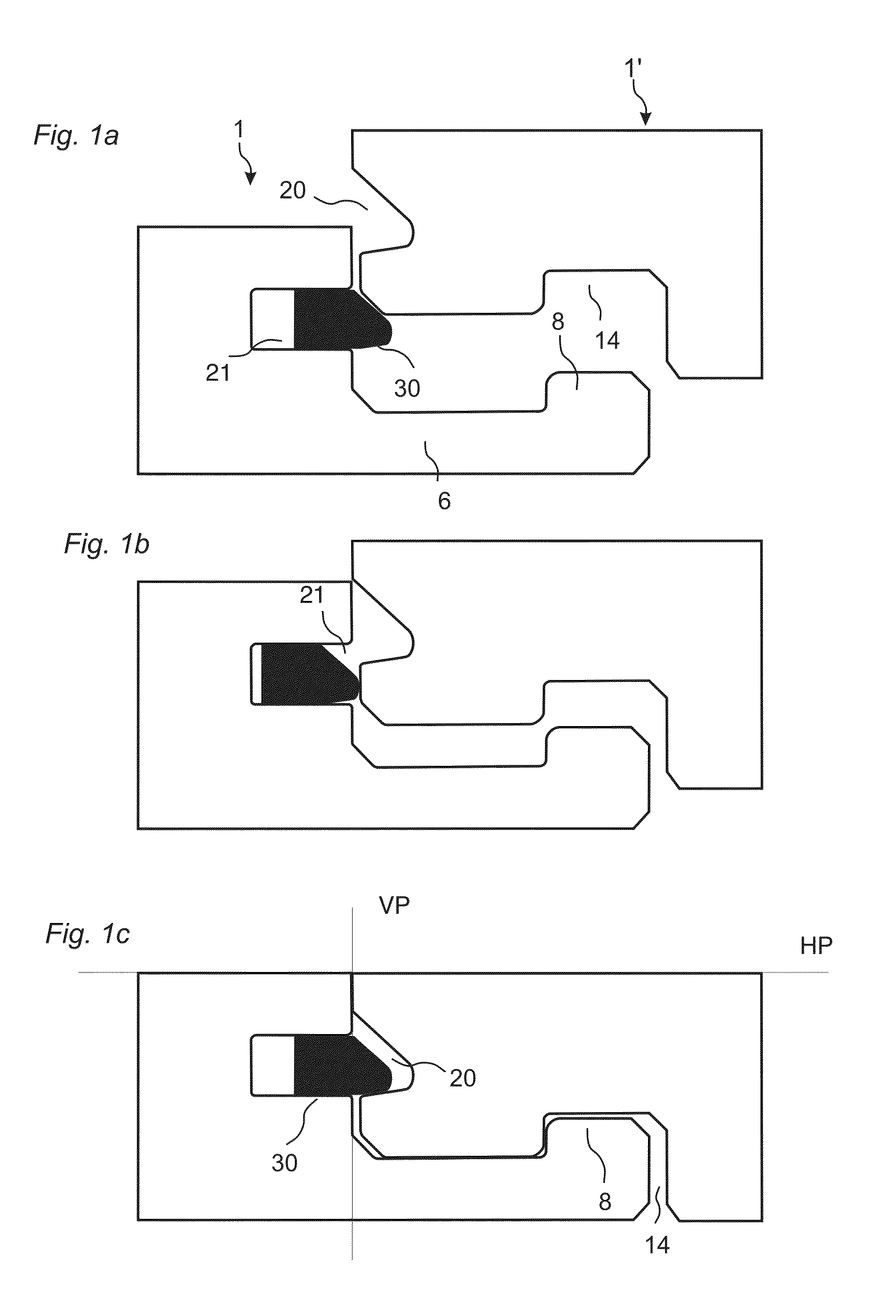
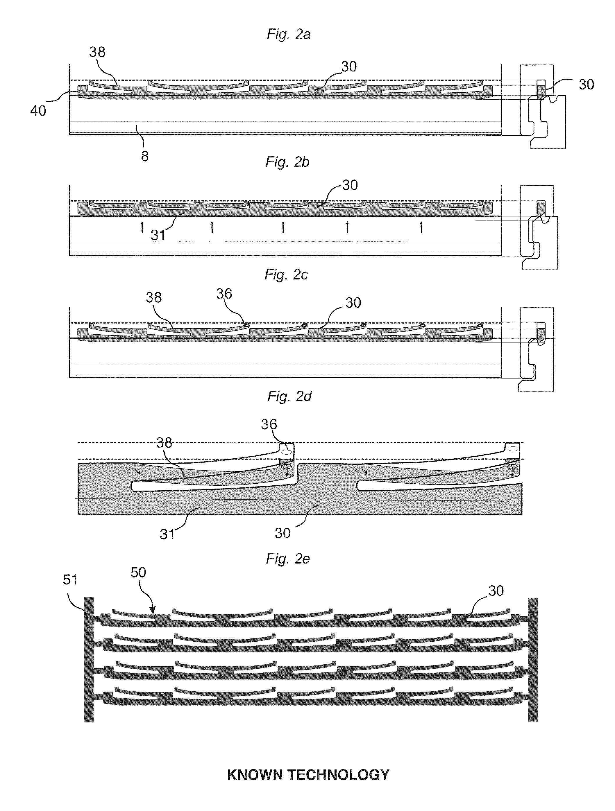
[0060]FIGS. 3a-3g show a first preferred embodiment of a displaceable tongue 30 which is intended to be used to lock two adjacent edges of two floor panels by a vertical displacement of the panels relative each other.

[0061]FIG. 3a show a displaceable tongue 30 with a main tongue body 31, a length direction L along the joint, a width W perpendicular to the length and parallel to a horizontal plane and a thickness perpendicular to the width. An inner vertical tongue plane Tp1 and an outer vertical tongue plane Tp2 parallel with the length direction of the tongue int...


PUM


Abstract

Building panels, especially floor panels are shown, which are provided with a vertical locking system on adjacent edges including a displaceable tongue that has a main tongue body and separate spring parts attached to the body.

Description

TECHNICAL FIELD[0001]The disclosure generally relates to the field of mechanical locking systems for floor panels and building panels. The disclosure shows floorboards, locking systems, installation methods and production methods.FIELD OF APPLICATION[0002]Embodiments of the present disclosure are particularly suitable for use in floating floors, which are formed of floor panels which are joined mechanically with a locking system integrated with the floor panel, i.e. mounted at the factory, are made up of one or more upper layers of wood or wood veneer, decorative laminate, powder based surfaces or decorative plastic material, an intermediate core of wood-fibre-based material or plastic material and preferably a lower balancing layer on the rear side of the core. Floor panels with a surface layer of cork, linoleum, rubber or soft wear layers, for instance needle felt glued to a board, printed and preferably also varnished surface and floors with hard surfaces such as stone, tile and ...

Claims


Application Information

Patent Timeline
IPC IPC(8): E04B1/38E04B5/00
CPCE04F15/02038E04F2201/0547E04F2201/0146
Inventor PERVAN, DARKOPERVAN, TONY
Owner CERALOC INNOVATION AB
Why Eureka
Try Eureka