Device for active heating of transparent materials

a technology of active heating and transparent materials, applied in the direction of ohmic resistance heating, ohmic resistance heating details, electrical appliances, etc., can solve the problems of affecting the appearance of objects, blurry and distorted objects, and bluffing, and is potentially dangerous to the viewer

Inactive Publication Date: 2013-02-21
ELSER JEREMY ALAN +1
View PDF13 Cites 15 Cited by
  • Summary
  • Abstract
  • Description
  • Claims
  • Application Information

AI Technical Summary

Benefits of technology

[0007]The above-described problems are addressed and a technical solution is achieved in the art by the active heating devices described herein. According to one or more embodiments of the present invention, a device for evaporating condensate from a surface is described which comprises a transparent base; a transparent thermo-resistive element having at least one positive electrode and at least one negative electrode, wherein the

Problems solved by technology

The formation of condensate (i.e., fogging) on surfaces of transparent objects such as windows, eyewear and face shields has long been a challenging problem.
Surface fogging acts to disperse light passing through transparent materials thereby causing objects to appear blurry and distorted when viewed through the material.
This bluffing can be inhaling and potentially dangerous to the viewer.
For example, fogging on automotive windows can severely obstruct a driver's view of the road and create dangerous driving conditions.
Fogging on athletic eyewear such as hockey face shields, motorcycle face shields and ski goggles can be equally inhaling and dangerous and detract from the enjoyment derived from engaging in activities requiring the use of such eyewear.
However, such chemical treatments are only minimally effective for preventing fogging and must be periodically reapplied to the transparent surface as the effectiveness of such chemical surface treatments decreases over time.
However, these cumbersome and heavy airgap systems are not suitable for use in performance sports such as hockey, lacrosse or American football and have thus been relegated primarily to motor sports applications where quick head movements are not generally required.
The inherent resistive properties of such thermo-resistive coatings causes the coatings to heat up when an electrical current is passed through them.
Such busbar

Method used


Image

  • Device for active heating of transparent materials
  • Device for active heating of transparent materials
  • Device for active heating of transparent materials

Examples


Embodiment Construction

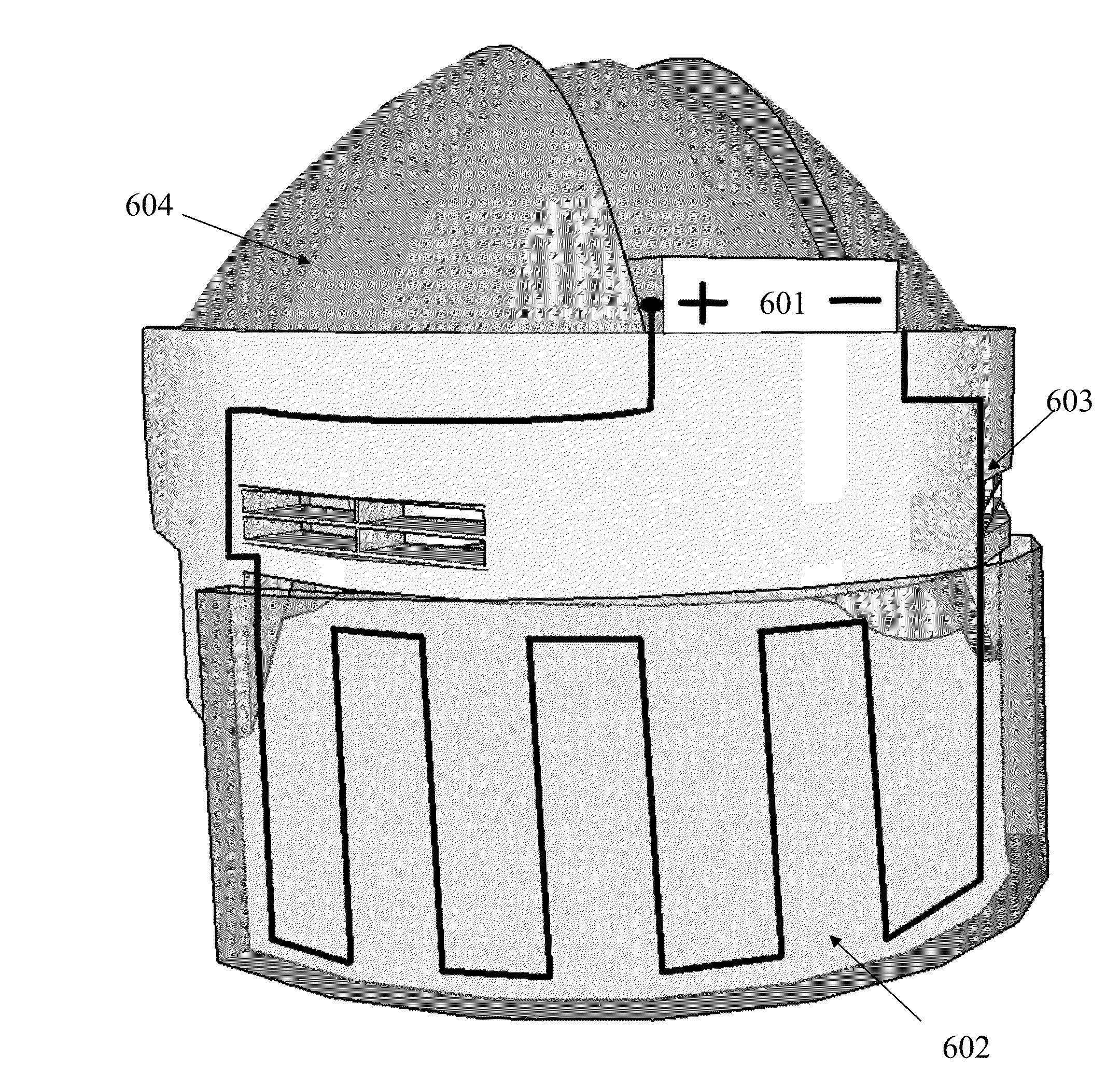
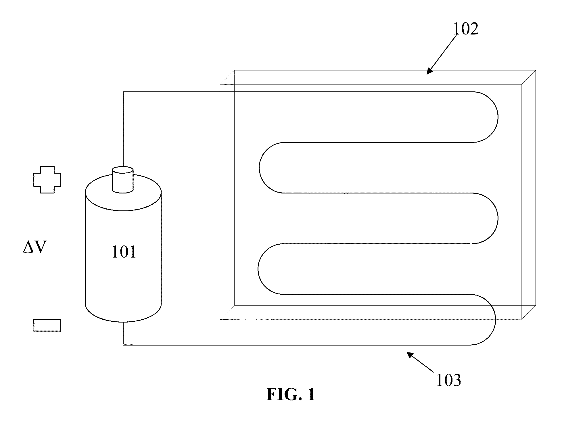
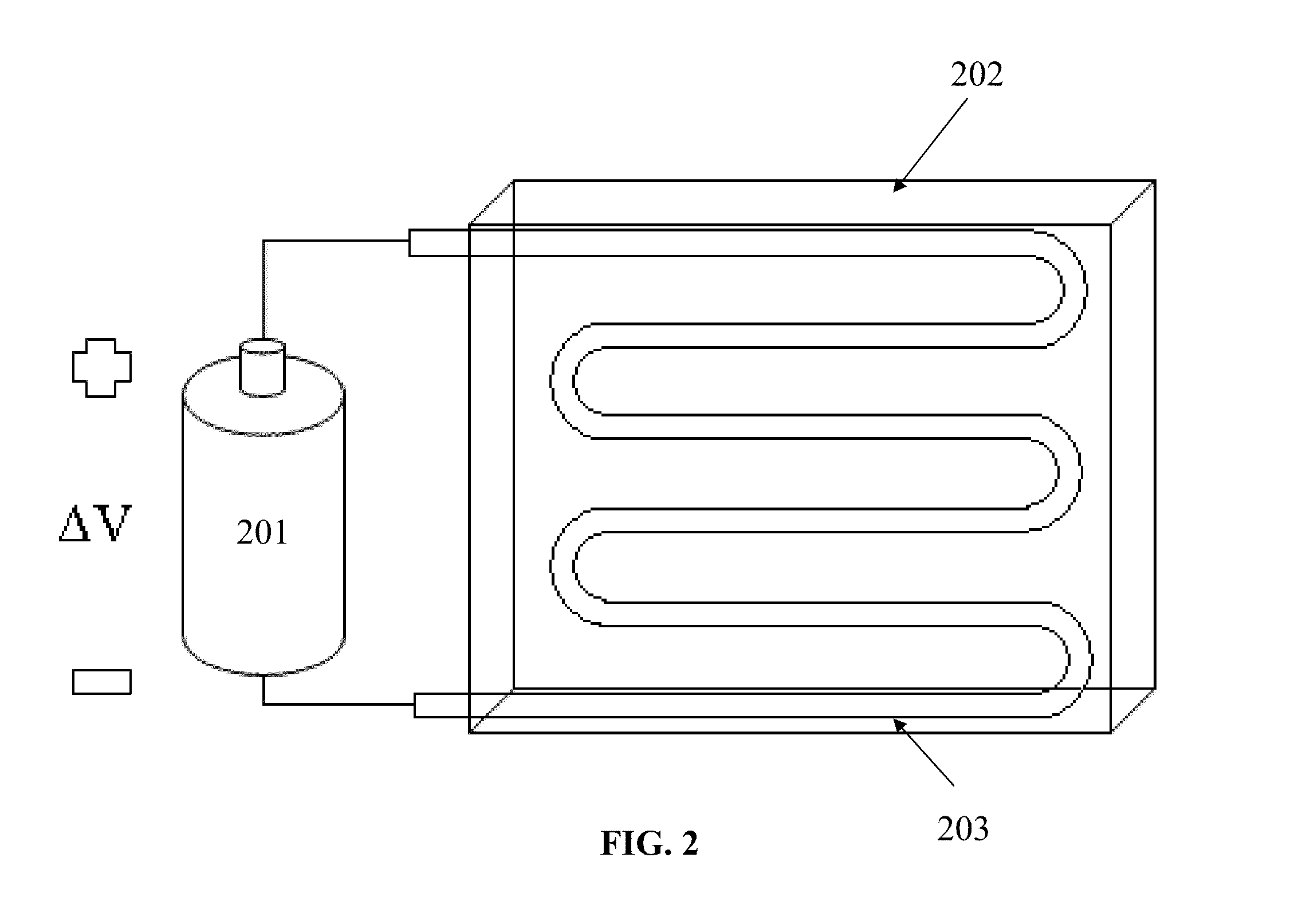
[0018]Embodiments of the present invention relate to devices for evaporating condensate from a surface of transparent base material. In one embodiment, a thermo-resistive element for heating the surface is made more scratch-resistant by embedding the thermo-resistive element directly into the transparent base. In another embodiment, a thermo-resistive element may be configured in such a way as to reduce the amount of electricity required to heat the element thereby reducing the size of any required external power source. In another embodiment, a thermo-resistive element may be configured in such a way as to selectively heat particular areas of the eyewear surface that are susceptible to condensation accumulation, namely near a wearer's nose and mouth.

[0019]Embodiments of the present invention relate to a device for heating a surface of a transparent base used in eyewear thereby preventing the accumulation of condensing fluids, generally water. The device comprises a transparent base...


PUM


Abstract

A device for removing condensate from a surface of a transparent material is disclosed. The device uses a power supply to conduct an electrical current through and thereby heat a transparent thermo-resistive element embedded within the transparent material. As the transparent thermo-resistive element is heated, heat transfers to a surface of the transparent material, thereby heating such surface to a temperature above the dew point of the condensing liquid which in turn prevents fogging on the surface of the transparent material. Embodiments of the present invention have utility in performance eyewear where fogging has the potential to reduce visibility.

Description

TECHNICAL FIELD[0001]The present invention relates generally to devices for removing condensate from surfaces of transparent materials, and more specifically, to devices for removing condensate from optical surfaces of eyewear.BACKGROUND[0002]The formation of condensate (i.e., fogging) on surfaces of transparent objects such as windows, eyewear and face shields has long been a challenging problem. Surface fogging acts to disperse light passing through transparent materials thereby causing objects to appear blurry and distorted when viewed through the material. This bluffing can be inhaling and potentially dangerous to the viewer. For example, fogging on automotive windows can severely obstruct a driver's view of the road and create dangerous driving conditions. Fogging on athletic eyewear such as hockey face shields, motorcycle face shields and ski goggles can be equally inhaling and dangerous and detract from the enjoyment derived from engaging in activities requiring the use of su...

Claims


Application Information

Patent Timeline
IPC IPC(8): H05B1/00H05B3/02
CPCH05B2203/013H05B3/84
Inventor ELSER, JEREMY ALANGLICK, FREDERICK LEONARD
Owner ELSER JEREMY ALAN
Why Eureka
Try Eureka