Dynamic targeting system with projectile-specific aiming indicia in a reticle and method for estimating ballistic effects of changing environment and ammunition

Active Publication Date: 2013-02-28
TUBB G DAVID
View PDF2 Cites 31 Cited by
  • Summary
  • Abstract
  • Description
  • Claims
  • Application Information

AI Technical Summary

Benefits of technology

[0043]Accordingly, it is an object of the present invention to overcome the above mentioned difficulties by providing a rapid and effective system and method for compensating for a gyroscopicall

Problems solved by technology

The variations in the anomalies were observed to be repeatable, and so a precise evaluation of the anomalies was undertaken

Method used


Image

  • Dynamic targeting system with projectile-specific aiming indicia in a reticle and method for estimating ballistic effects of changing environment and ammunition
  • Dynamic targeting system with projectile-specific aiming indicia in a reticle and method for estimating ballistic effects of changing environment and ammunition
  • Dynamic targeting system with projectile-specific aiming indicia in a reticle and method for estimating ballistic effects of changing environment and ammunition

Examples


Embodiment Construction

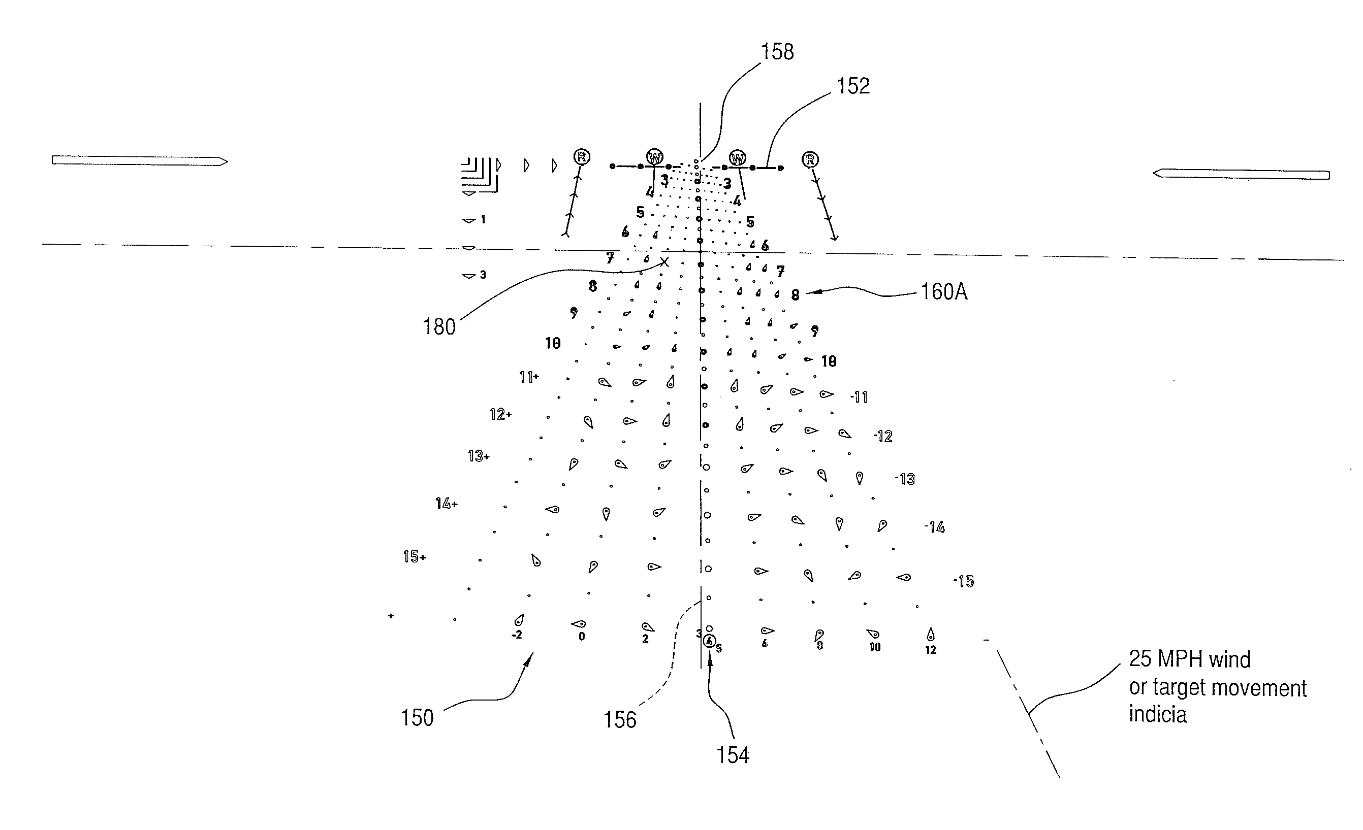
[0081]Applicant's reticle as shown in FIGS. 2-19 (e.g. 200, 300 or DTR reticle 700) is configured for use in a novel aiming system providing a two-dimensional array of aiming indicia showing many predicted Center of Impact (or “COI”) references for a user's projectile (e.g., 26) and the user expresses the firing solution or Hold Point for a selected target solely in dimensions of distance and velocity. The reticle system of the present invention is configured to be superimposed on an Aiming Area viewed by the user (e.g., through riflescope 10). The Aiming Area includes at least one selected Target (e.g. 8) or Point of Aim (“POA”). The user determines the effective range to the Target and estimates the wind's effect to select an aiming Hold Point for the user's projectile. The “Hold Point” or firing solution is expressed as one point corresponding to (1) an identified effective range (e.g., yards or meters) and (2) an effective crosswind velocity (e.g., in MPH). Additionally, applica...


PUM


Abstract

A dynamic ballistic effect compensating reticle and an aim compensation method for use in rifle sights or projectile weapon aiming systems includes a multiple point elevation and windage aim point field including a primary aiming mark indicating a primary aiming point adapted to be sighted-in at a first selected range (e.g., 200 yds) and a plurality secondary aiming point arrays beneath the primary aiming mark. The method for compensating for a projectile's ballistic behavior while developing a field expedient firing solution permits the shooter to express the field expedient firing solution in units of distance, (e.g., yards or meters, when describing or estimating range and nominal air density ballistic characteristics), and velocity (e.g., mph or kph, for windage hold points). The reticle aim point field permits the marksman to adjust the firing solution for momentary atmospheric effects and operational contingencies such as variations in ammunition.

Description

PRIORITY CLAIMS AND CROSS-REFERENCE TO RELATED APPLICATIONS[0001]This application claims priority to and is related to co-pending:[0002](1) commonly owned U.S. provisional patent application No. 61 / 490,916, filed May 27, 2011, (2) commonly owned U.S. provisional patent application No. 61 / 553,161, filed Oct. 29, 2011 and (3) commonly owned U.S. provisional patent application No. 61 / 582185, filed Dec. 30, 2011, the entire disclosures of which are incorporated herein by reference.BACKGROUND OF THE INVENTION[0003]1. Field of the Invention[0004]The present invention relates to optical instruments and methods for aiming a rifle, external ballistics and methods for predicting a gyroscopically stabilized projectile's trajectory to a target. This application relates to projectile weapon aiming systems such as rifle scopes, to reticle configurations for projectile weapon aiming systems, and to associated methods of compensating for a projectile's external ballistic behavior while developing a...

Claims


Application Information

Patent Timeline
IPC IPC(8): F41G1/38F41G1/00
CPCF41G1/38
Inventor TUBB, G. DAVID
Owner TUBB G DAVID
Why Eureka
Try Eureka