
Dielectric coating and application process

a technology of dielectric coating and application process, which is applied in the direction of coatings, lifting devices, building rescue, etc., can solve the problems of poor aesthetic value, easy damage, and large volume of plastic covers used to protect exposed electrically-conductive materials, and may pass a long time before such is noticed and replaced

Inactive Publication Date: 2013-02-28
ALTEC INDS
View PDF24 Cites 21 Cited by
  • Summary
  • Abstract
  • Description
  • Claims
  • Application Information

AI Technical Summary

Benefits of technology

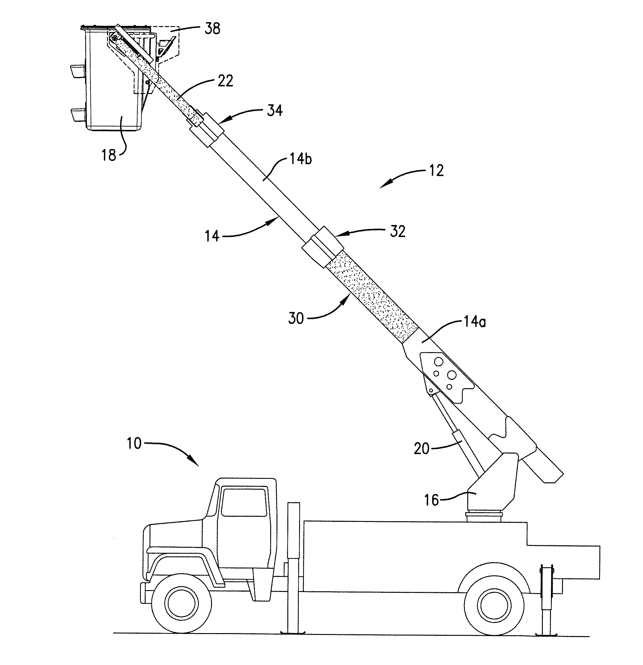
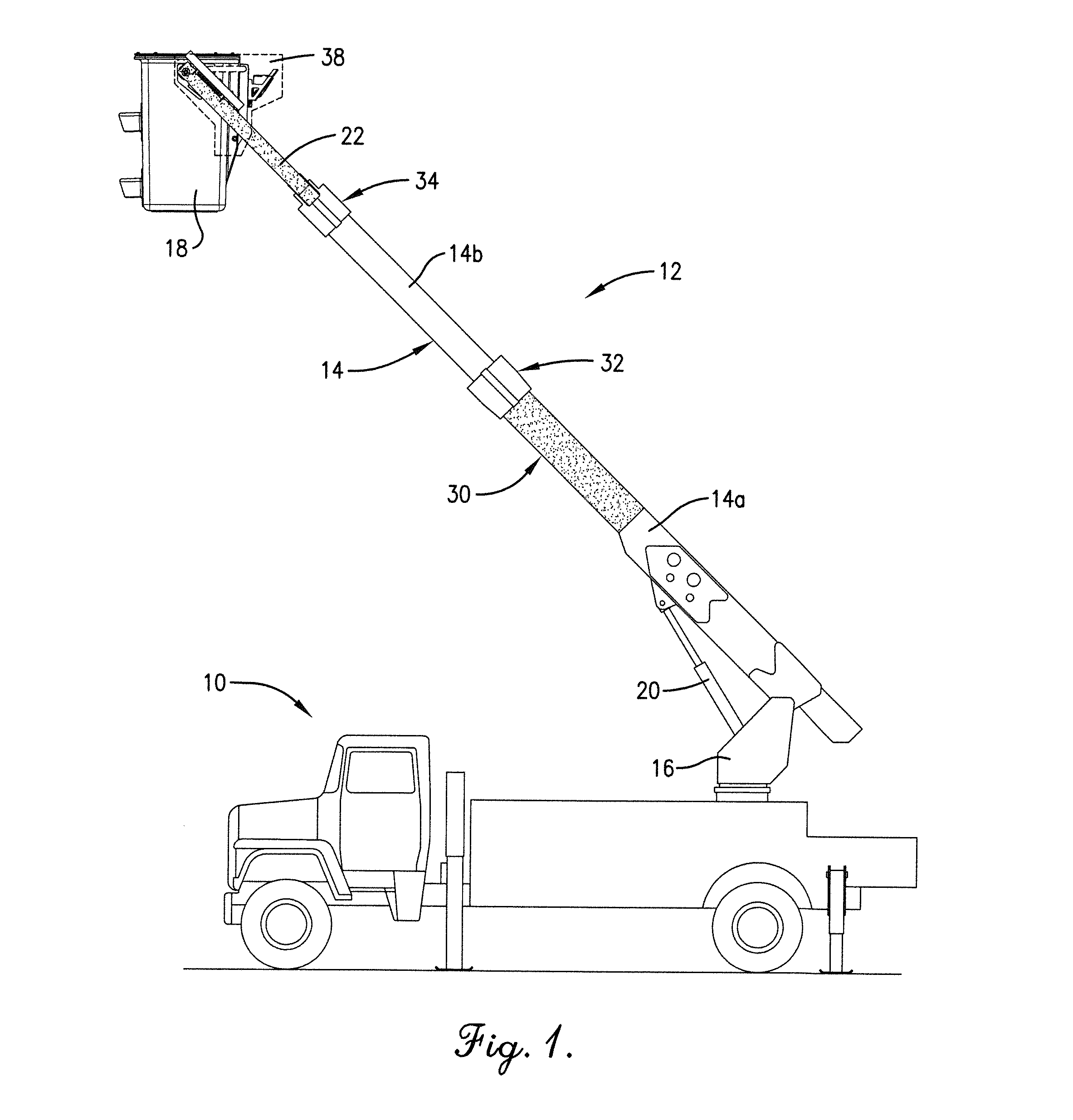
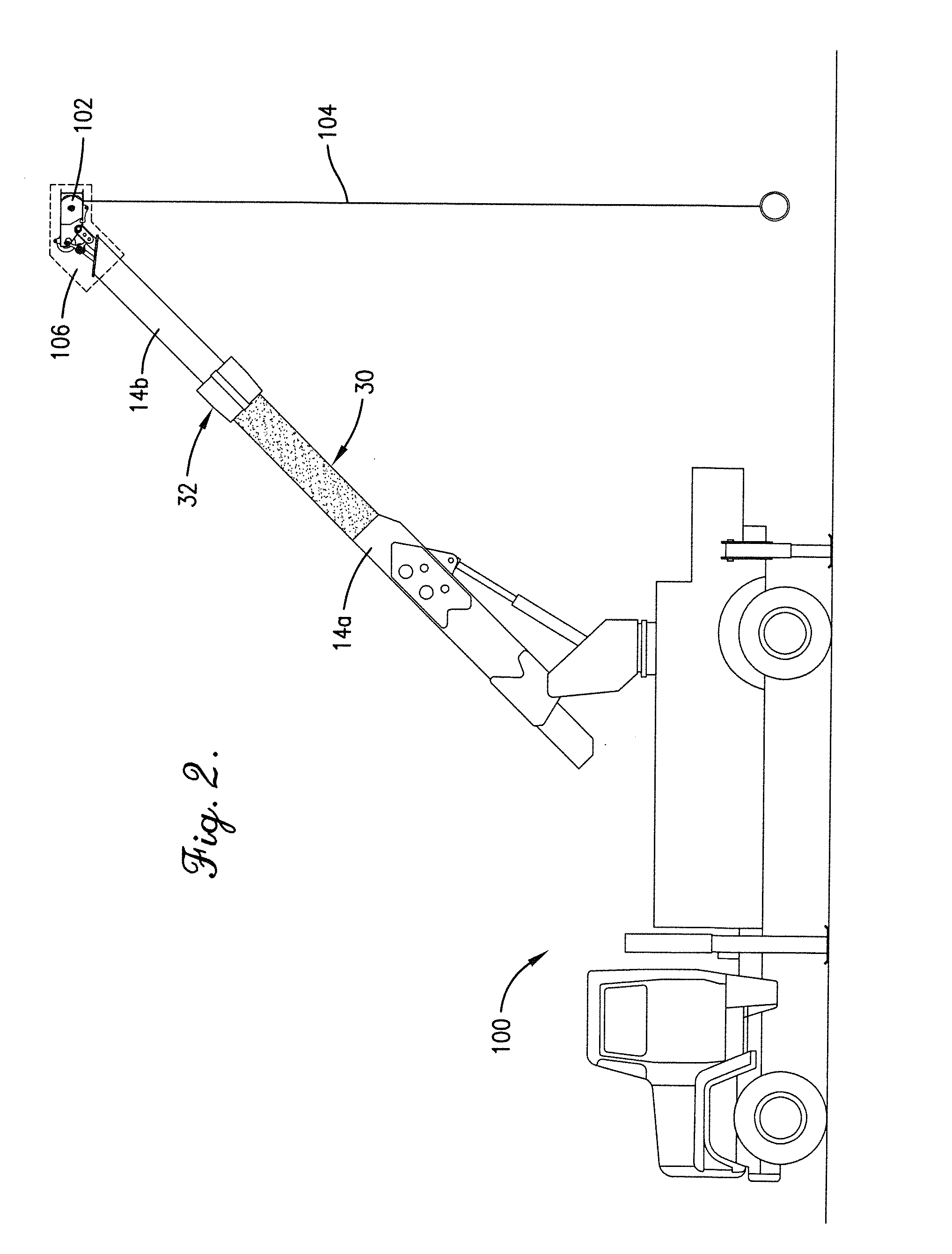
The invention relates to a method of coating a boom assembly component with a seamless layer of dielectric material and a layer of ultraviolet radiation protective material. This creates an electrically insulating barrier around the component to protect it from electrical arcing or other electrical hazards. The invention also involves coating the outer surface of the lower boom section with a layer of polyurethane and a layer of ultraviolet radiation protective material. This creates a dielectric barrier around the portion of the boom that is most prone to electrical hazards. The invention also provides a boom assembly that includes a lower boom section coated with a layer of dielectric material and a layer of ultraviolet radiation protective material. The invention also relates to a utility vehicle with a boom assembly coated with a seamless layer of dielectric material and a layer of ultraviolet radiation protective material. The technical effects of this invention are to provide a safer and reliable boom assembly for use in various applications that reduces the risk of electrical hazards and improves operational efficiency.

Problems solved by technology

The plastic covers used to protect exposed electrically-conductive material are bulky, of poor aesthetic value, easily damaged, and expensive to replace.
If a plastic cover becomes damaged, for instance, due to regular wear and tear, a period of time may pass before such is noticed and replaced.
Sometimes, it may be difficult to observe small cracks in plastic covers.
If the damaged plastic cover results in exposure of an electrically-conductive part, personnel utilizing the aerial device are at an increased risk of electrocution until the damaged plastic cover is replaced.
Such inspection and replacement tasks are time consuming and result in considerable downtime of the aerial device, which decreases efficiency and is costly.

Method used


Image

  • Dielectric coating and application process
  • Dielectric coating and application process
  • Dielectric coating and application process

Examples


Embodiment Construction

[0020]The following detailed description references the accompanying drawings that illustrate specific embodiments in which the invention may be practiced. The embodiments are intended to describe aspects of the invention in sufficient detail to enable those skilled in the art to practice the invention. Other embodiments can be utilized and changes can be made without departing from the scope of the present invention. The following detailed description is, therefore, not to be taken in a limiting sense. The scope of the present invention is defined only by the appended claims, along with the full scope of equivalents to which such claims are entitled.

[0021]In this description, references to “one embodiment”, “an embodiment”, or “embodiments” mean that the feature or features being referred to are included in at least one embodiment of the technology. Separate references to “one embodiment”, “an embodiment”, or “embodiments” in this description do not necessarily refer to the same em...


PUM


Abstract

A method of electrically insulating one or more components of a boom assembly involves applying a seamless coating of dielectric material to an outer surface of each of one or more boom assembly components, the boom assembly components being constructed of metal or other electrically conductive material. The dielectric material is applied as a liquid and, when hardened, creates a seamless, electrically insulating barrier on the boom assembly components to which it is applied. A layer of ultraviolet radiation protective material may be applied on top of the layer of dielectric material to protect the dielectric material from ultraviolet degradation. The boom assembly components may be painted or otherwise treated prior to the application of the dielectric material.

Description

RELATED APPLICATIONS[0001]This non-provisional patent application claims priority benefit with regard to all common subject matter of earlier-filed U.S. Provisional Patent Application No. 61 / 528,982, filed Aug. 30, 2011 and entitled DIELECTRIC COATING AND APPLICATION PROCESS. The earlier-filed provisional application is hereby incorporated by reference in its entirety into the present application.BACKGROUND[0002]1. Field[0003]Embodiments of the present invention relate to a dielectric coating and application process to provide an electrically insulating coating, thus heightening safety in applications involving electric circuits. More particularly, the present invention provides an elastomeric coating and application process to provide an insulating barrier to electrically conductive components of an aerial device being utilized by an operator during a construction or maintenance operation in or around an electrical environment.[0004]2. Related Art[0005]In the electrical and telecom...

Claims


Application Information

Patent Timeline
IPC IPC(8): B05D7/00B66C23/687B66F13/00
CPCB66F17/006B66C23/701B66F11/046
Inventor THOMPSON, JESSE L.
Owner ALTEC INDS
Learn More