Illumination apparatus

a technology of illumination apparatus and abrasives, which is applied in the direction of lighting and heating apparatus, fixed installation, instruments, etc., can solve the problems of low light use efficiency and poor visual quality of illumination apparatus, and achieve the effect of preventing the decrease of light use efficiency

Inactive Publication Date: 2013-02-28
PANASONIC CORP
View PDF2 Cites 13 Cited by
  • Summary
  • Abstract
  • Description
  • Claims
  • Application Information

AI Technical Summary

Benefits of technology

[0015]The illumination apparatus may further include a diffusing transmission member which diffuses a light emitted from the light guide plate. With the illumination apparatus in accordance with the aspect of the present invention, the lights incident from the light sources into the auxiliary light guide part of the light guide plate are emitted toward the central portion of the housing, and the lights incident from the light sources into the main light guide part of the light guide plate are guided toward the outer periphery of the light guide plate and are diffused and emitted from a light emission surface of the main light guide part. As a result, the lights from the light sources can be uniformly irradiated from the entire surface of the illumination apparatus. In addition, since the lights incident from the light sources into the light guide plate can be directly irradiated from the auxiliary light guide part, it is possible to prevent decrease in light use efficiency.

Problems solved by technology

For that reason, when the illumination apparatus 101 is turned on, the central portion becomes dark, and thus the illumination apparatus 101 shows poor visual quality as compared to, e.g., conventional ceiling lights using a ring-like fluorescent lamp as a light source.
However, in the illumination apparatus disclosed in Japanese Patent No. 4066702, the light guide plate and the reflector overlap with each other in the light irradiation direction and some of the lights incident from the light sources into the light guide plate shuttles between the light guide plate and the reflector, which shows low light use efficiency.

Method used


Image

  • Illumination apparatus
  • Illumination apparatus
  • Illumination apparatus

Examples


first embodiment

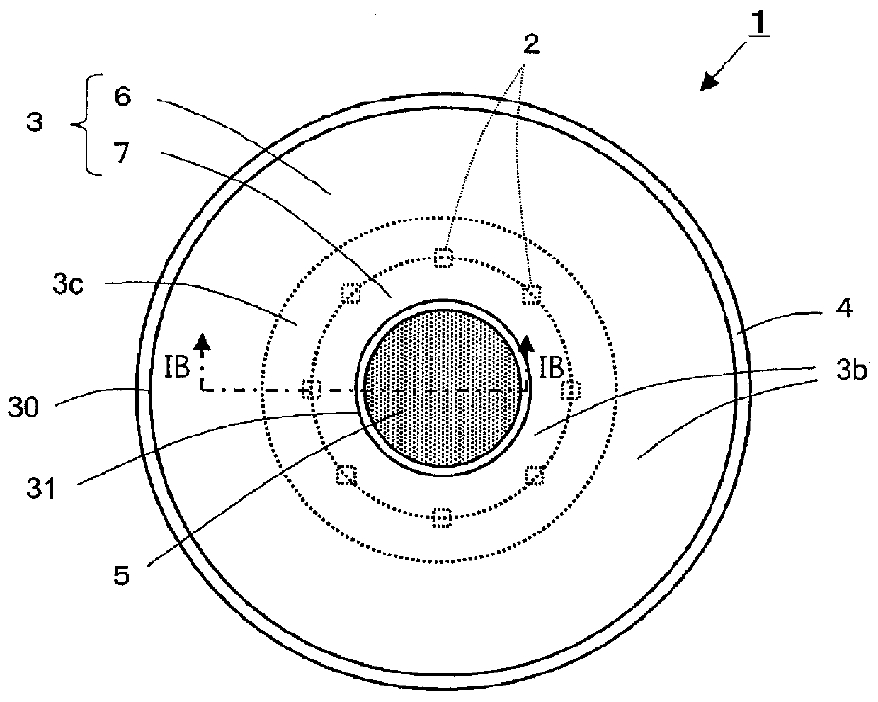
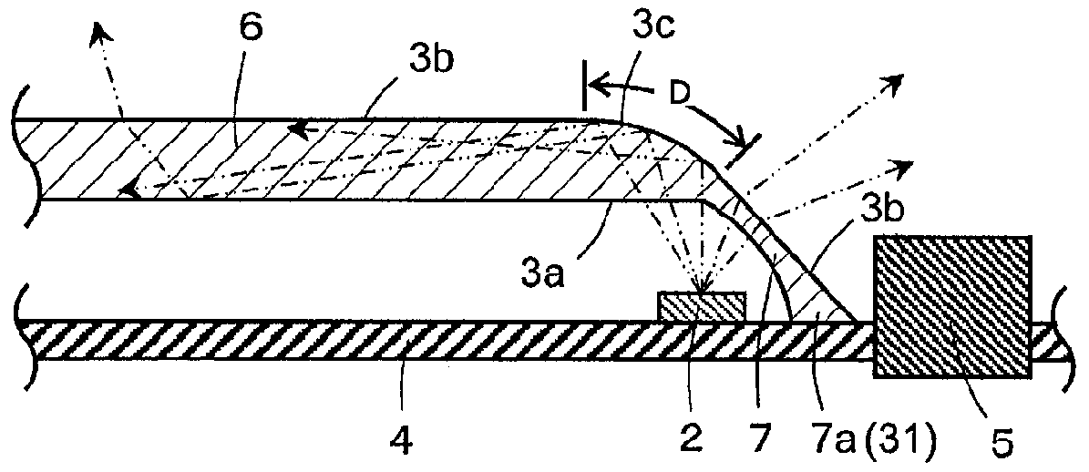
[0023]An illumination apparatus in accordance with the present invention will now be described with reference to FIGS. 1A to 1C which form a part hereof. In the following description, an illumination apparatus 1 of this embodiment will be illustrated with a ceiling light. The illustration apparatus 1 includes light sources 2; a light guide plate 3 which guides light from the light sources 2; a housing 4 which holds the light sources 2 and the light guide plate 3; and an apparatus attachment part 5 provided in a central portion of the housing 4.

[0024]The light sources 2 are arranged in the form of a ring at the front side of the housing 4 around the apparatus attachment part 5, and the light guide plate 3 is arranged outside the apparatus attachment part 5 in such a way as to face the housing 4 and cover the front side of the light sources 2. That is, the light guide plate 3 is arranged to face the housing 4 except the apparatus attachment part 5 provided in the central portion of th...

second embodiment

[0044]Next, an illumination apparatus in accordance with the present invention will be described with reference to FIGS. 2A and 2B. In an illumination apparatus 1 in accordance with this embodiment, a light guide plate 3 includes transmission surfaces 8 which are interposed between total-reflective surfaces 3c to transmit and externally emit incident lights with no total-reflection. Each of the transmission surfaces 8 have a stepped plane in parallel to the housing 4, which is formed between the corresponding total-reflective surfaces 3c.

[0045]Further, in this embodiment, a light incidence surface 3a of an auxiliary light guide part 7 has a convex shape and a light emission surface 3b of the auxiliary light guide part 7 has a convex shape as well. The light incidence surface 3a of the auxiliary light guide part 7 continues to a light incidence surface 3a of a main light guide part 6 in a bent manner, and the light emission surface 3b of the auxiliary light guide part 7 also continu...

third embodiment

[0048]Next, an illumination apparatus in accordance with the present invention will be described with reference to FIGS. 3A and 3B. In an illumination apparatus 1 in accordance with this embodiment, a light guide plate 3 includes a lateral light guide part 9 which is integrated with a main light guide part 6 in the periphery of the main light guide part 6 and emits incident light toward the outer periphery of the housing 4. The lateral light guide part 9 is inclined toward the outer periphery of the housing 4, forming an acute angle with the housing 4, and has a concave light emission surface 31b formed in its outer peripheral end 9a (the outer peripheral end 30) side; and a convex light emission surface 32b formed in the main light guide part 6 side.

[0049]Light sources 2 are arranged along the lateral light guide part 9. An auxiliary light guide part 7 is inclined toward the outer periphery of the housing 4, forming an acute angle with the housing 4, and has a convex light emission...


PUM


Abstract

An illumination apparatus includes light sources; a light guide plate guiding lights from the light sources; a housing holding the light sources and the light guide plate;
and an apparatus attachment part. The light sources are arranged around the apparatus attachment part 5, and the light guide plate 3 is provided outside the apparatus attachment part to face the housing and cover a front side of the light sources. The light guide plate includes a main light guide part guiding lights from the light sources toward an outer periphery of the light guide plate and scattering and emitting the lights to a surface of the main light guide part; and an auxiliary light guide part integrated with the main light guide part at an inner peripheral side of the main light guide part and guiding and emitting the lights from the light sources toward the central portion of the housing.

Description

FIELD OF THE INVENTION[0001]The present invention relates to an illumination apparatus which is capable of providing a uniform irradiation of light from a light source.BACKGROUND OF THE INVENTION[0002]In recent years, domestic main illumination apparatuses such as ceiling lights using light emitting diodes (LEDs) as a light source has been in wide use. FIG. 6 shows such one conventional illumination apparatus 101. The illumination apparatus 101 includes an illumination module (not shown) including LEDs as a light source; a transparent cover 102 which transmits light from the illumination module; a housing 103 which holds the illumination module and the transparent cover 102; and a center cover 104 which is made of an opaque material and covers a central portion of the housing 103. In the central portion of the housing 103 covered with the center cover 104, there are provided a power supply unit which supplies a power to the illumination module and an apparatus attachment part which ...

Claims


Application Information

Patent Timeline
Patent Type & Authority Applications(United States)
IPC IPC(8): F21V8/00F21V13/02
CPCF21K9/52F21S8/04F21V3/02F21V5/045F21V7/0016F21V7/0091F21V2200/20F21Y2101/02F21Y2103/022G02B6/0068G02B6/0073F21V2200/15G02B6/0021F21K9/61F21Y2103/33F21Y2115/10
Inventor NAKAMURA, KYOHEIYAMAUCHI, SATORUOKADA, TOSHIZUMIYAMAOKA, HIROYUKI
Owner PANASONIC CORP
Why Eureka
Try Eureka