Electronic device with sound chamber

a technology of electronic devices and sound chambers, applied in the direction of transducer details, electrical transducers, electrical apparatus, etc., can solve the problems of unsatisfactory sound and difficulty in assembly

Inactive Publication Date: 2013-02-28
HONG FU JIN PRECISION IND (SHENZHEN) CO LTD +1
View PDF3 Cites 6 Cited by
  • Summary
  • Abstract
  • Description
  • Claims
  • Application Information

AI Technical Summary

Problems solved by technology

However, gluing the foam increases the difficulty of assembly, and furthermore, usually causes unsatisfactorily sound due to poor sealing.

Method used


Image

  • Electronic device with sound chamber
  • Electronic device with sound chamber
  • Electronic device with sound chamber

Examples


Embodiment Construction

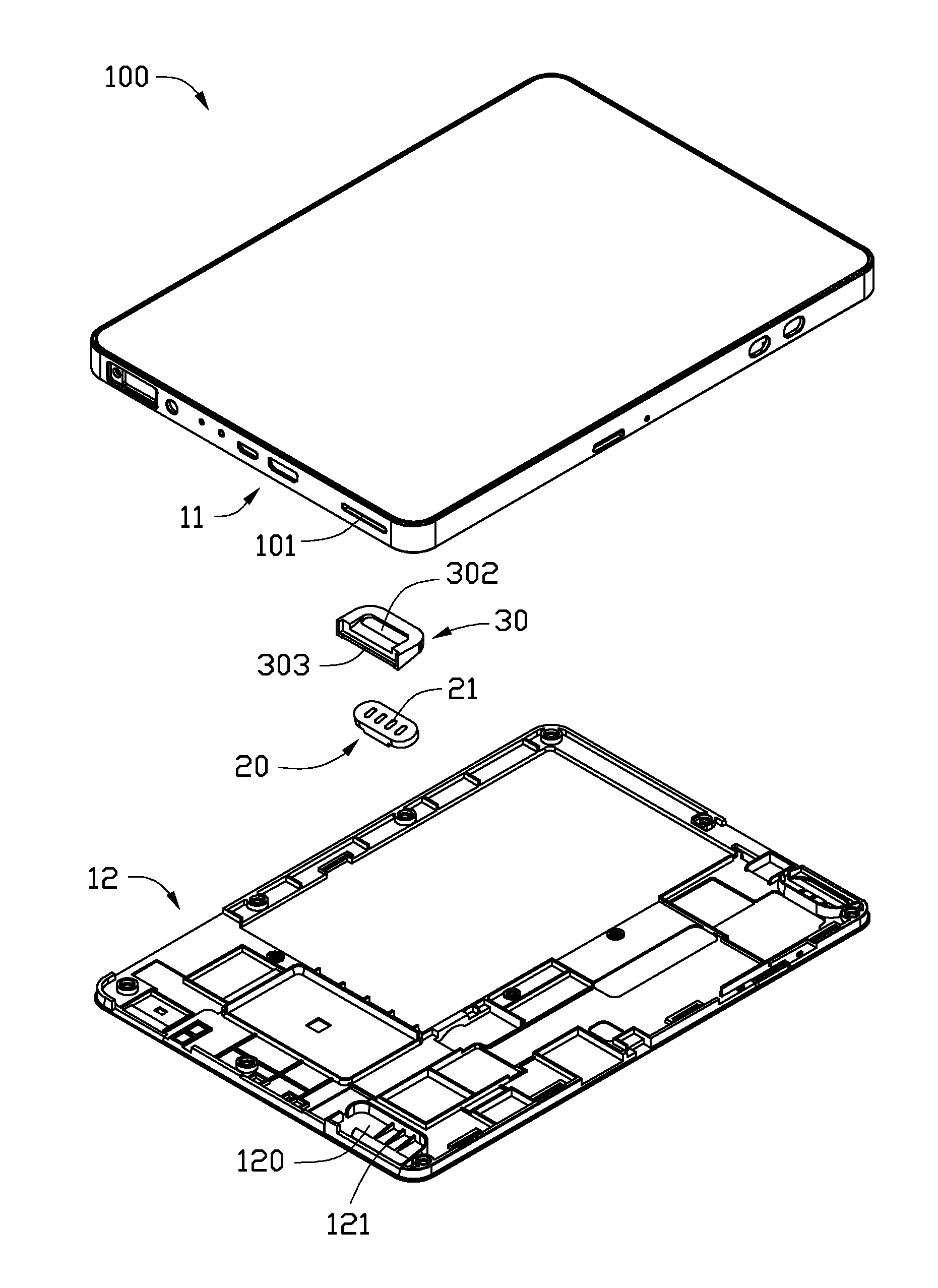
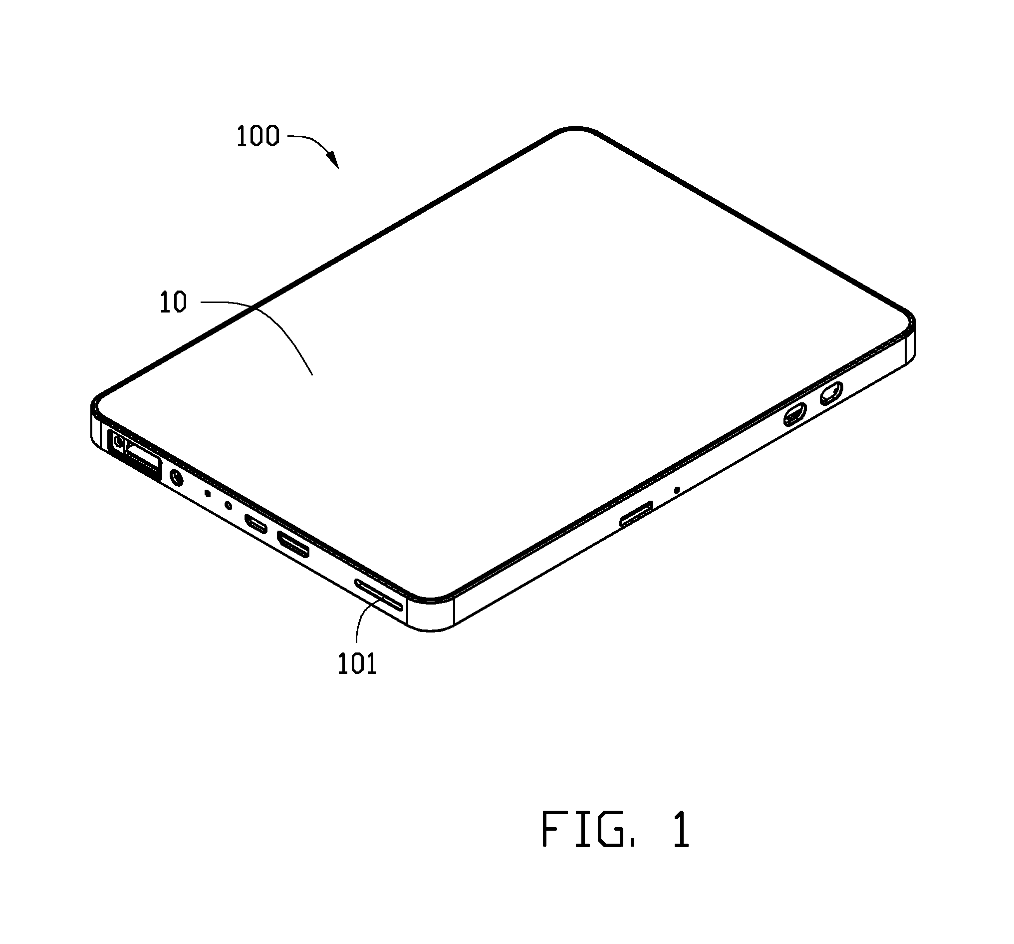
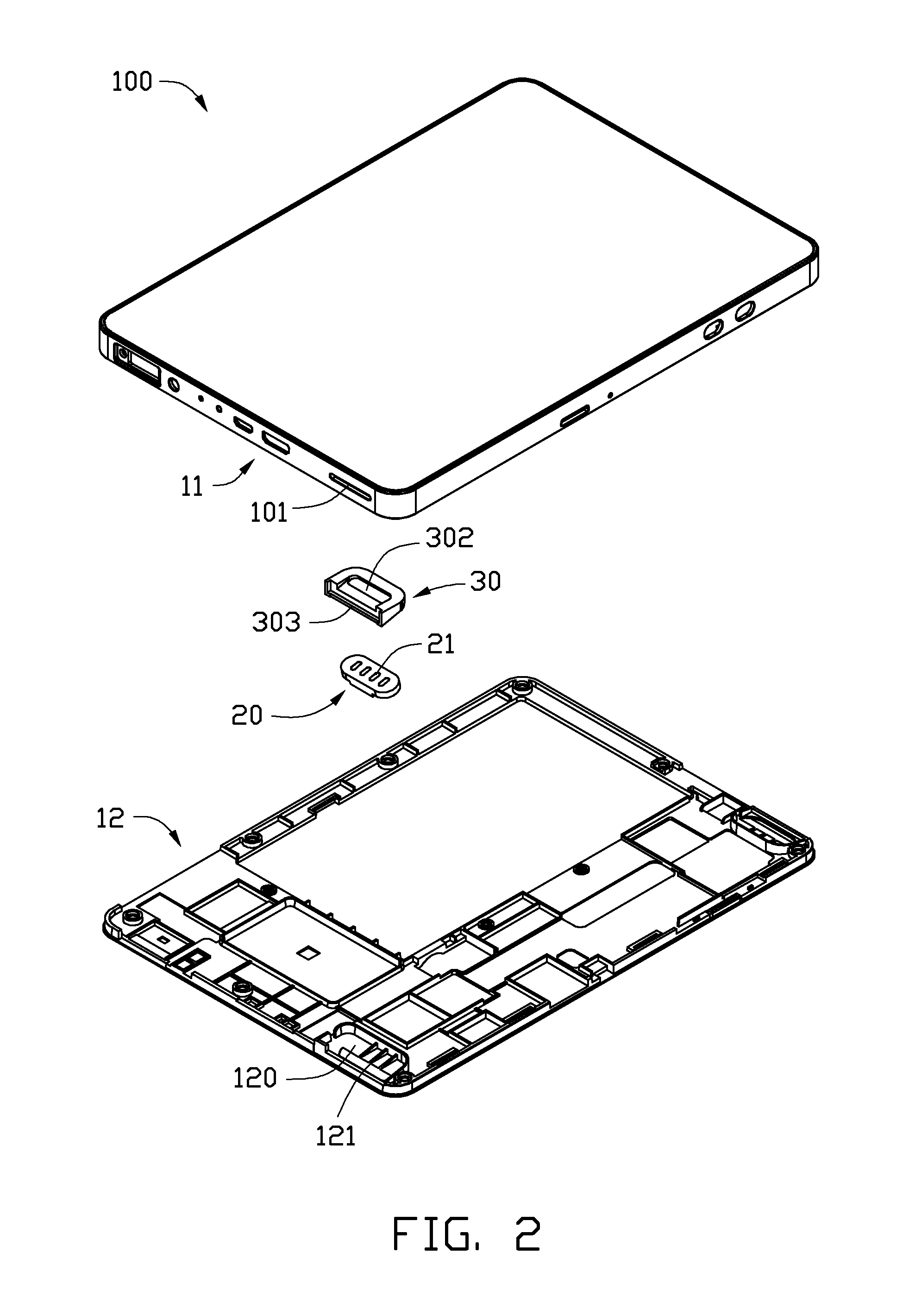
[0011]Referring to FIGS. 1 and 2, an electronic device 100 is disclosed as an exemplary embodiment. The electronic device 100 includes a enclosure 10 defining an exposed slot 101, a speaker 20 fixed in the enclosure 10, and a rubber element 30 received in the enclosure 10. The electronic device 100 is an electronic reader. In an alternative embodiment, the electronic device 100 can be a mobile phone, a tablet computer, or a music player.

[0012]Referring to FIGS. 2 and 3, the enclosure 10 includes an upper cover 11 and a lower cover 12 fixed to the upper cover 11. The lower cover 12 defines a rectangular space 120. A support member 121 for supporting the speaker 20 protrudes from the bottom of the space 120. The slot 101 is defined in the sidewall of the upper cover 11. The upper cover 11 further defines a receiving space 110 located corresponding to the space 120, for receiving the rubber element 30. A restricting member 112 vertically protrudes from an edge of the receiving space 11...


PUM


Abstract

An electronic device includes an enclosure, a speaker fixed in the enclosure, and a rubber element. The enclosure defines an exposed slot, and a speaker receiving chamber communicating with the slot. The speaker includes a first surface and a opposite second surface. The speaker is configured for radiating sound at the first surface. The rubber element includes a main body a recess and a through hole penetrating through a bottom of the recess. The speaker is inserted in the recess with the first surface facing the bottom of the recess. The combined the speaker and the rubber element are engagingly received in the speaker receiving chamber.

Description

BACKGROUND[0001]1. Technical Field[0002]The present disclosure relates to electronic devices, and particularly, to an electronic device with a sound chamber.[0003]2. Description of Related Art[0004]Electronic devices such as digital photo frames, tablet computers, electronic books, mobile phones, and MP3 players typically include a speaker. The electronic devices usually include a enclosure, and a middle frame fixed in the enclosure and defining a chamber. The speaker is fixed on the middle frame and faces the chamber. The speaker together with the enclosure and the middle frame define a front chamber and a back chamber. Foam is arranged between the enclosure and the middle frame to seal the front and the back chambers. However, gluing the foam increases the difficulty of assembly, and furthermore, usually causes unsatisfactorily sound due to poor sealing.[0005]Therefore, what is needed is an electronic device alleviating the limitations described above.BRIEF DESCRIPTION OF THE DRAW...

Claims


Application Information

Patent Timeline
Patent Type & Authority Applications(United States)
IPC IPC(8): H04R1/02
CPCH04R1/2803H04R2499/15H04R2499/11
Inventor YANG, HE-HUIHU, YONG-HUIWU, KAI-KUEIHSIEH, KUN-CHIH
Owner HONG FU JIN PRECISION IND (SHENZHEN) CO LTD
Why Eureka
Try Eureka