Image Heating Apparatus

a heating apparatus and image technology, applied in the field of image heating apparatus, can solve the problems of unsatisfactory user experience, standby time, and unsatisfactory

Inactive Publication Date: 2013-02-28
CANON KK
View PDF8 Cites 12 Cited by
  • Summary
  • Abstract
  • Description
  • Claims
  • Application Information

AI Technical Summary

Benefits of technology

[0010]The present invention provides an image heating apparatus configured to perform two functions, that is, a function of separating a sheet from an image heating member and a function of lowering a target temperature of the image heating member, without upsizing the image heating apparatus.

Problems solved by technology

When an image is formed on such a thin recording medium, an undesired phenomenon may occur such that the recording medium heated and pressurized by a fixing device (image heating apparatus) is wrapped around a fixing member (image heating member) and is not separated from the fixing member.
Such a problem similarly occurs when a borderless image having no margin on a leading edge portion of the recording medium is formed.
Such a standby time may lower user satisfaction.

Method used


Image

  • Image Heating Apparatus
  • Image Heating Apparatus
  • Image Heating Apparatus

Examples


embodiment 1

[0065]FIG. 5 is an explanatory graph showing performance of cooling the fixing roller by the air separation unit. FIG. 6 is a flowchart illustrating cooling control of the fixing roller according to Embodiment 1.

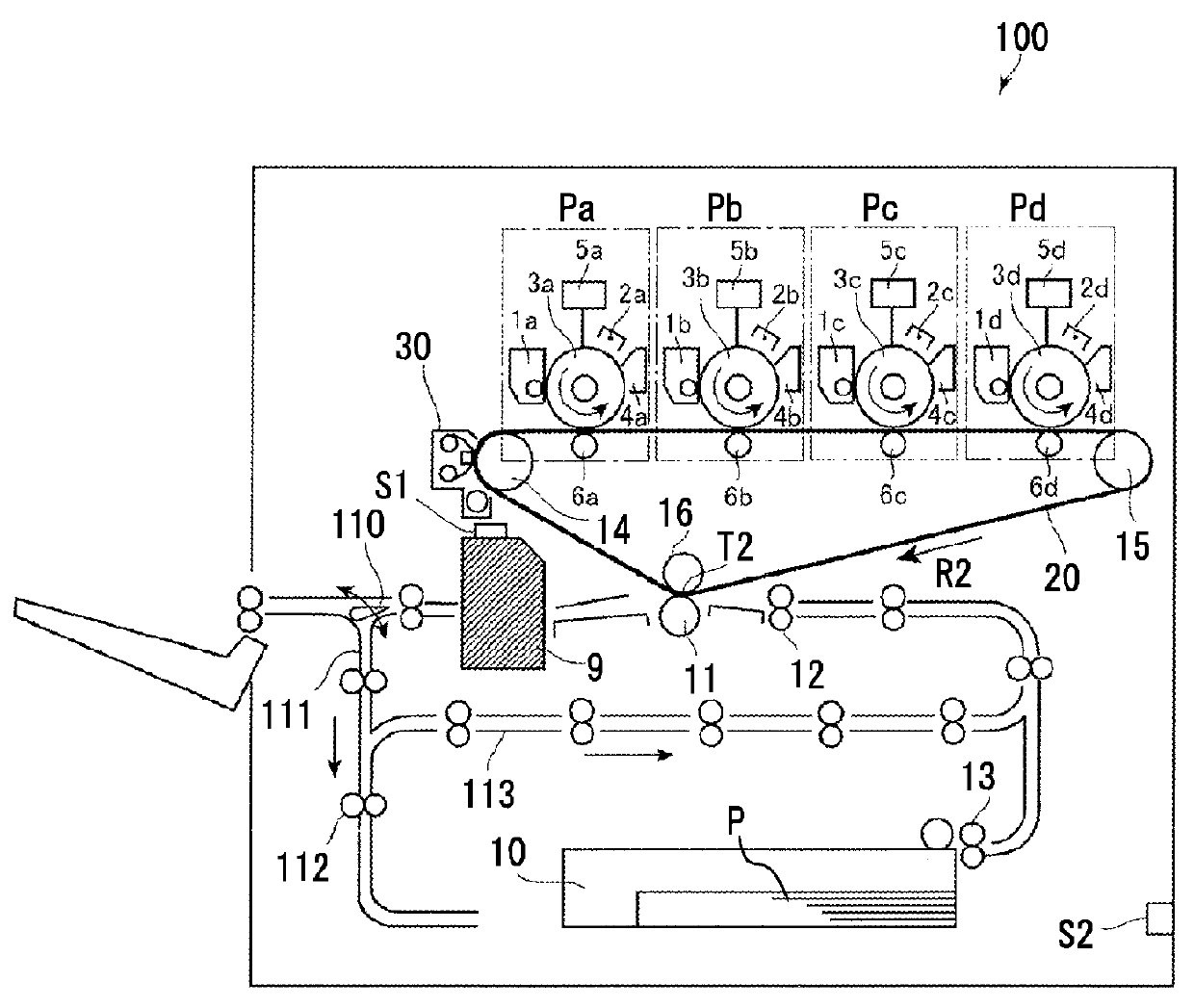
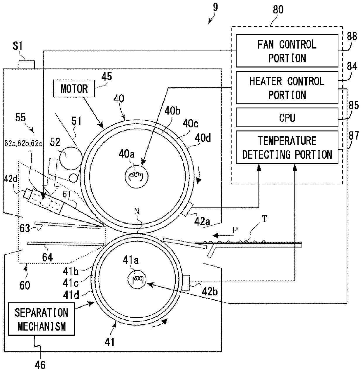
[0066]As illustrated in FIG. 2, the fixing roller 40 abuts on an image surface of the recording medium. The pressure roller 41 forms the heating nip N for the recording medium by abutting on the fixing roller 40. The lamp heater 40a heats the fixing roller 40 to control its temperature to a variable controlled temperature. The secondary transfer roller 11 which is an example of a feeding portion feeds the recording medium to the heating nip N after waiting for the temperature of the fixing roller 40 to be controlled to the controlled temperature.

[0067]In a case that meets predetermined conditions in which separation of the recording medium from the fixing roller 40 is difficult, the air separation unit 60 which is an example of the blowing device separates the recording medi...

embodiment 2

[0091]FIG. 7 is an explanatory graph showing a relationship between a temperature difference and an air flow rate according to Embodiment 2 of the present invention. In Embodiment 1, the ON and OFF of the air separation unit 60 is controlled. In Embodiment 2, the air flow rate is changed in accordance with the temperature difference between two controlled temperatures before and after the change. With this control, excessive cooling of the fixing roller by the air separation unit 60 can be avoided by adjusting a speed of the temperature change of the fixing roller.

[0092]Embodiment 2 has the same configuration and the same control as Embodiment 1 except that the air flow rate adjustment of the air separation unit 60 in Steps S5, S8, and S9 in the flowchart illustrated in FIG. 6 are added. Therefore, in the following description, matters different from Embodiment 1 are described and redundant description is omitted.

[0093]As shown in FIG. 7, there was determined a condition for achievi...

embodiment 3

[0111]In the control of Embodiment 2, in order to avoid excessive cooling or temperature fluctuation of the fixing roller 40, the control portion 80 decreases the air flow rate of the air separation unit 60 as the temperature difference between the controlled temperatures before and after the change is smaller. When the controlled temperature of the fixing roller 40 is changed from a low controlled temperature to a high controlled temperature, a fan operation target temperature of the fixing roller 40 to be controlled is provided, and the operating condition of the air separation unit 60 is changed by comparing the fan operation target temperature and the temperature of the fixing roller 40.

[0112]However, as a temperature of the outside air is lower, the cooling performance with respect to the fixing roller 40 is increased, but in a usual air separating operation, there occurs a problem that the temperature of the fixing roller 40 cannot be maintained in a stable manner. In addition...


PUM


Abstract

An image heating apparatus including: an image heating member configured to heat an image on a sheet; a heating device configured to heat the image heating member so that a temperature of the image heating member is kept to a target temperature; an air blowing device configured to blow an air toward the image heating member when a predetermined sheet is separated from the image heating member; and an actuating device configured to actuate the air blowing device to cool the image heating member by blowing the air when the target temperature of the image heating member is lowered.

Description

BACKGROUND OF THE INVENTION[0001]1. Field of the Invention[0002]The present invention relates to an image heating apparatus configured to heat an image on a sheet. The image heating apparatus may be used as a fixing device in an image forming apparatus such as a copier, a printer, a facsimile (FAX), and a multifunction peripheral (MFP) having multiple forgoing functions.[0003]2. Description of the Related Art[0004]In recent years, there has been such a demand that an electrophotographic image forming apparatus can form an image on a recording medium (sheet) that is thinner than a conventional recording medium.[0005]When an image is formed on such a thin recording medium, an undesired phenomenon may occur such that the recording medium heated and pressurized by a fixing device (image heating apparatus) is wrapped around a fixing member (image heating member) and is not separated from the fixing member. Such a problem similarly occurs when a borderless image having no margin on a lead...

Claims


Application Information

Patent Timeline
Patent Type & Authority Applications(United States)
IPC IPC(8): G03G15/20
CPCG03G15/2046G03G15/2028G03G15/2021G03G21/206G03G15/2064G03G2221/1645
Inventor CHIYODA, YASUHARU
Owner CANON KK
Why Eureka
Try Eureka