Control device for internal combustion engine

a control device and internal combustion engine technology, applied in the direction of electric control, ignition automatic control, instruments, etc., can solve the problems of more difficult knocking, more difficult knocking, and more difficult knocking

Inactive Publication Date: 2019-08-06
TOYOTA JIDOSHA KK
View PDF23 Cites 0 Cited by
  • Summary
  • Abstract
  • Description
  • Claims
  • Application Information

AI Technical Summary

Benefits of technology

[0010]The disclosure provides a control device for an internal combustion engine that can efficiently prevent the occurrence of knocking by properly controlling both the ignition crank angle and the cooling water temperature.
[0032]According to the control device for an internal combustion engine according to this aspect, the target temperature of the first cooling system can be decreased corresponding to the tendency of the occurrence of knocking. Therefore, both the first cooling system and the second cooling system can be properly controlled at temperatures suitable for prevention of knocking.

Problems solved by technology

It is known that, in an internal combustion engine, as the ignition crank angle is more retarded, knocking is more difficult to occur while fuel consumption is deteriorated.
It is also known that as the cooling water temperature decreases, the in-cylinder temperature decreases so that knocking is more difficult to occur.
When knocking has occurred in the above-mentioned conventional internal combustion engine, a state in which knocking is difficult to occur is created by both the retard of the ignition crank angle and the decrease in the cooling water temperature.

Method used


Image

  • Control device for internal combustion engine
  • Control device for internal combustion engine
  • Control device for internal combustion engine

Examples


first embodiment

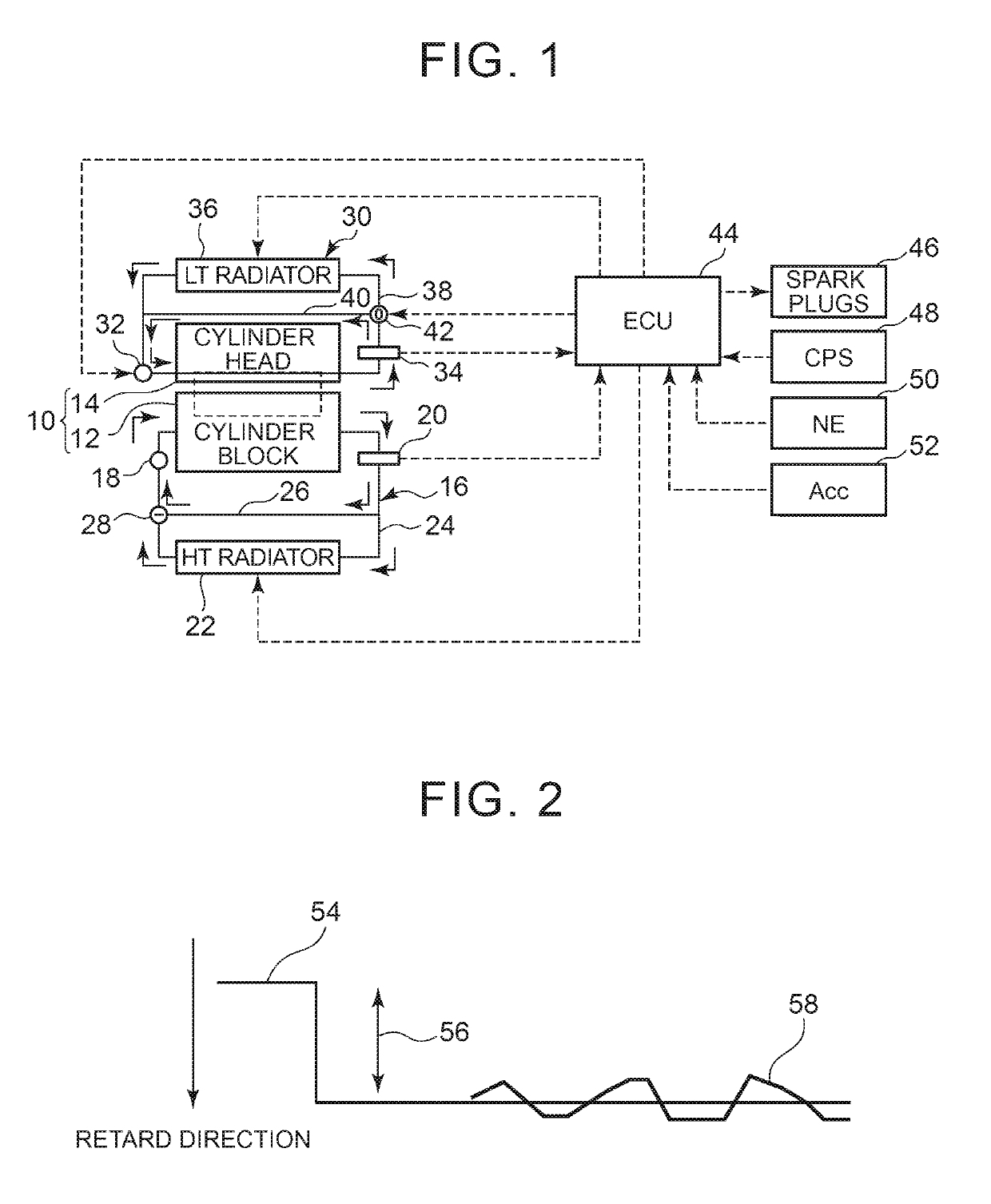
[0045]FIG. 1 is a diagram showing the configuration of the disclosure. As shown in FIG. 1, a system of this embodiment includes an internal combustion engine 10. The internal combustion engine 10 is an engine that is used while mounted on a vehicle, and includes a cylinder block 12 and a cylinder head 14. Cooling water passages independent of each other are respectively formed in the cylinder block 12 and the cylinder head 14.

[0046]The cooling water passage of the cylinder block 12 constitutes part of a HT (High Temperature) system 16 configured to mainly cool the cylinder block 12. The HT system 16 includes a water pump (W / P) 18 on the inlet side of the cylinder block 12. The W / P 18 is mechanically driven by the internal combustion engine 10 so as to be able to discharge cooling water in the HT system 16 toward the cylinder block 12.

[0047]A HT water temperature sensor 20 is provided on the outlet side of the cylinder block 12. The HT water temperature sensor 20 produces an ethwH si...

second embodiment

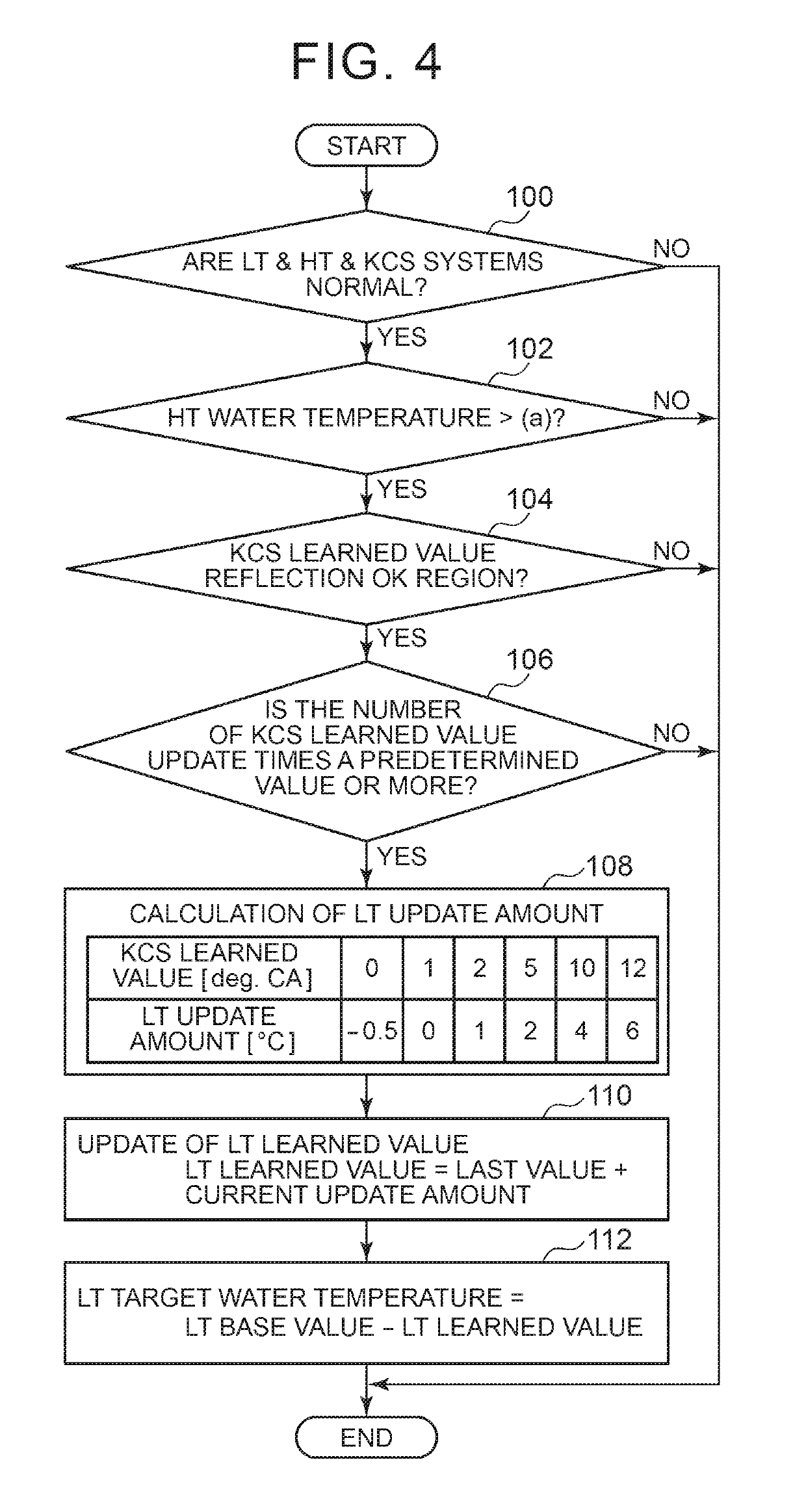
[0117]In the second embodiment described above, a “cooling command supply system” is realized by the implementation of the routine shown in FIG. 7 by the ECU 44. Further, the LT update amount map shown in the frame of step 108 corresponds to an “update rule.”

[0118]Next, a third embodiment of the disclosure will be described with reference to FIG. 8. A system of this embodiment can be realized by causing the ECU 44 to implement a routine shown in FIG. 8 instead of the routine shown in FIG. 4 in the configuration of the first embodiment.

[0119]In the first embodiment described above, the object of the correction based on the KCS learned value (i.e., a “command value”) is the LT target water temperature. On the other hand, the system of this embodiment has a feature in that an object of correction based on a KCS learned value is, instead of a LT target water temperature, a Duty signal for the E-W / P 32 that is set based on the LT target water temperature.

[0120]That is, when the feedback ...

third embodiment

[0126]In the third embodiment described above, the object of the correction based on the KCS learned value is limited to the Duty signal, but its object is not limited thereto. That is, the cooling capacity of the LT system 30 can also be enhanced by a state of the three-way valve 42 or a state of the fan of the LT radiator 36. Therefore, the correction based on the KCS learned value may be applied to an opening degree of the three-way valve 42 or a drive signal of the radiator fan.

[0127]The above-mentioned modifications of the first embodiment can all be used as modifications of the third embodiment. The method of the second embodiment that calculates the KCS learned value per operating region and calculates the “command value” per operating region can be combined with the method that applies the correction based on the KCS learned value to the Duty signal.

[0128]In the third embodiment described above, a “cooling command supply system” is realized by the implementation of the routi...


PUM


Abstract

A control device for an internal combustion engine includes a knock control system, a cooling system, and an electronic control unit. The knock control system is configured to ignite a spark plug an ignition crank angle obtained by retarding the ignition crank angle in response to an occurrence of the knocking. The electronic control unit is configured to supply a command value corresponding to a target value of a cooling parameter to the cooling system such that the cooling system performs cooling of the internal combustion engine according to the command value. The electronic control unit is configured to correct the command value based on a KCS learned value such that as the KCS learned value increases, a correction amount for correcting the command value increases in correction amount in a direction in which a cooling capacity of the cooling system increases.

Description

INCORPORATION BY REFERENCE[0001]The disclosure of Japanese Patent Application No. 2015-114740 filed on Jun. 5, 2015 including the specification, drawings and abstract is incorporated herein by reference in its entirety.BACKGROUND OF THE DISCLOSURE[0002]1. Field of the Disclosure[0003]The disclosure relates to a control device for an internal combustion engine and, in particular, relates to a control device suitable for controlling an internal combustion engine mounted on a vehicle.[0004]2. Description of Related Art[0005]Japanese Patent Application Publication No. 2001-304028 (JP 2001-304028 A) discloses an internal combustion engine having both a function of retarding an ignition crank angle according to the knock intensity and a function of decreasing a target value of cooling water temperature according to the knock intensity. It is known that, in an internal combustion engine, as the ignition crank angle is more retarded, knocking is more difficult to occur while fuel consumptio...

Claims


Application Information

Patent Timeline
Patent Type & Authority Patents(United States)
IPC IPC(8): F02P5/15F02D41/06F02P17/12F01P7/04F01P7/16F02P5/152F01P3/02F01P5/10F01P5/12
CPCF02P5/1502F01P7/04F01P7/167F02D41/06F02P5/152F02P17/12F02P2017/128F01P2003/027F01P2005/105F01P2005/125F01P2037/00F02P5/1523F01P7/165F01P7/14F02D37/02Y02T10/40F01P5/12F02D35/027F02D41/2438F02D43/00G01L23/22
Inventor KITAYAMA, TAKESHIYAMASHITA, YOSHIYUKIFURUYA, YOSHIHIROMURATA, HIROKI
Owner TOYOTA JIDOSHA KK
Why Eureka
Try Eureka