Control device for internal combustion engine
- Summary
- Abstract
- Description
- Claims
- Application Information
AI Technical Summary
Benefits of technology
Problems solved by technology
Method used
Image
Examples
first embodiment
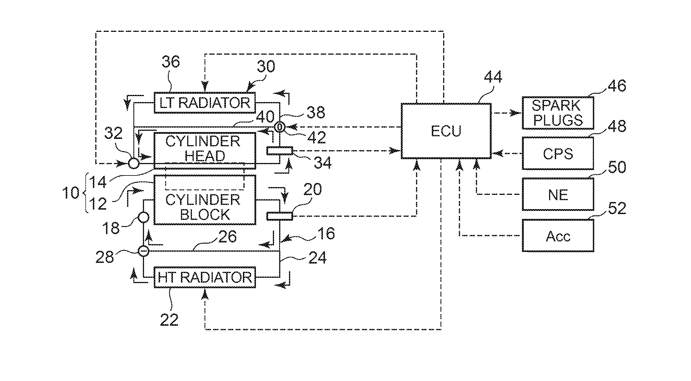
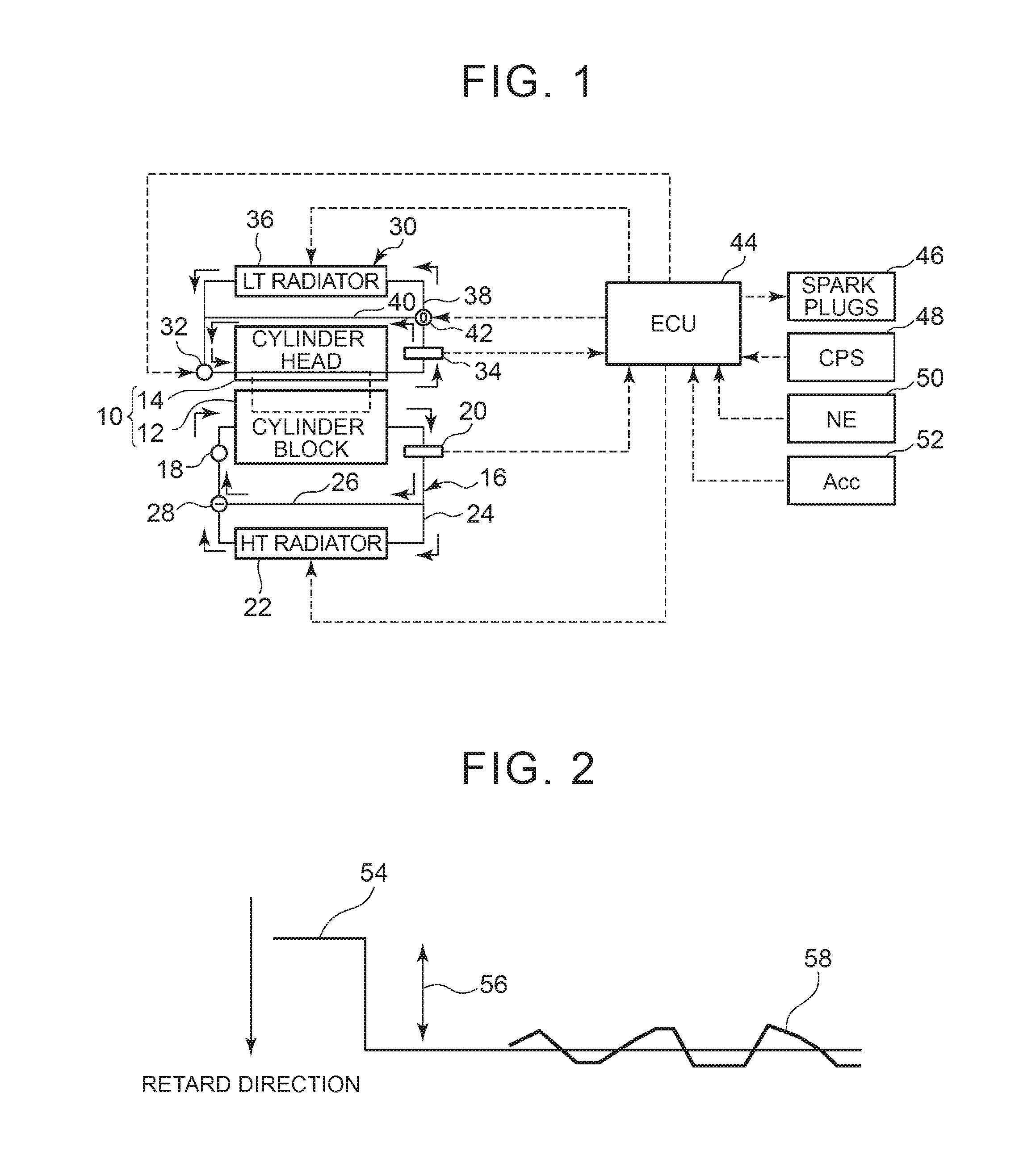
[0045]FIG. 1 is a diagram showing the configuration of the disclosure. As shown in FIG. 1, a system of this embodiment includes an internal combustion engine 10. The internal combustion engine 10 is an engine that is used while mounted on a vehicle, and includes a cylinder block 12 and a cylinder head 14. Cooling water passages independent of each other are respectively formed in the cylinder block 12 and the cylinder head 14.
[0046]The cooling water passage of the cylinder block 12 constitutes part of a HT (High Temperature) system 16 configured to mainly cool the cylinder block 12. The HT system 16 includes a water pump (W / P) 18 on the inlet side of the cylinder block 12. The W / P 18 is mechanically driven by the internal combustion engine 10 so as to be able to discharge cooling water in the HT system 16 toward the cylinder block 12.
[0047]A HT water temperature sensor 20 is provided on the outlet side of the cylinder block 12. The HT water temperature sensor 20 produces an ethwH si...
second embodiment
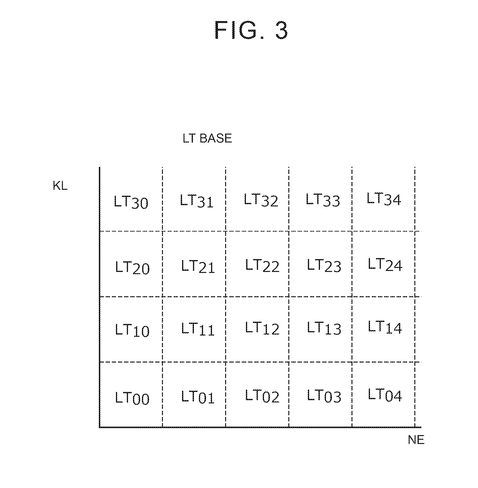
[0117]In the second embodiment described above, a “cooling command supply system” is realized by the implementation of the routine shown in FIG. 7 by the ECU 44. Further, the LT update amount map shown in the frame of step 108 corresponds to an “update rule.”
[0118]Next, a third embodiment of the disclosure will be described with reference to FIG. 8. A system of this embodiment can be realized by causing the ECU 44 to implement a routine shown in FIG. 8 instead of the routine shown in FIG. 4 in the configuration of the first embodiment.
[0119]In the first embodiment described above, the object of the correction based on the KCS learned value (i.e., a “command value”) is the LT target water temperature. On the other hand, the system of this embodiment has a feature in that an object of correction based on a KCS learned value is, instead of a LT target water temperature, a Duty signal for the E-W / P 32 that is set based on the LT target water temperature.
[0120]That is, when the feedback ...
third embodiment
[0126]In the third embodiment described above, the object of the correction based on the KCS learned value is limited to the Duty signal, but its object is not limited thereto. That is, the cooling capacity of the LT system 30 can also be enhanced by a state of the three-way valve 42 or a state of the fan of the LT radiator 36. Therefore, the correction based on the KCS learned value may be applied to an opening degree of the three-way valve 42 or a drive signal of the radiator fan.
[0127]The above-mentioned modifications of the first embodiment can all be used as modifications of the third embodiment. The method of the second embodiment that calculates the KCS learned value per operating region and calculates the “command value” per operating region can be combined with the method that applies the correction based on the KCS learned value to the Duty signal.
[0128]In the third embodiment described above, a “cooling command supply system” is realized by the implementation of the routi...
PUM
 Abstract
Description
Claims
Application Information
 - R&D
- Intellectual Property
- Life Sciences
- Materials
- Tech Scout
- Unparalleled Data Quality
- Higher Quality Content
- 60% Fewer Hallucinations
Browse by: Latest US Patents, China's latest patents, Technical Efficacy Thesaurus, Application Domain, Technology Topic, Popular Technical Reports.
© 2025 PatSnap. All rights reserved.Legal|Privacy policy|Modern Slavery Act Transparency Statement|Sitemap|About US| Contact US: help@patsnap.com


