
Inflatable ball with rib structure

Inactive Publication Date: 2013-02-28
LO JACK CORPORATION
View PDF9 Cites 22 Cited by
  • Summary
  • Abstract
  • Description
  • Claims
  • Application Information

AI Technical Summary

Benefits of technology

The present invention aims to provide an inflatable ball with a rib structure that is strong and easy to make.

Problems solved by technology

During this process, contamination is likely to occur, and offensive odor is created during burning, thereby causing harmful effects on human body.

Method used


Image

  • Inflatable ball with rib structure
  • Inflatable ball with rib structure
  • Inflatable ball with rib structure

Examples


Embodiment Construction

[0032]Before this invention is described in detail, it should be noted that, in the following description, similar elements are designated by the same reference numerals.

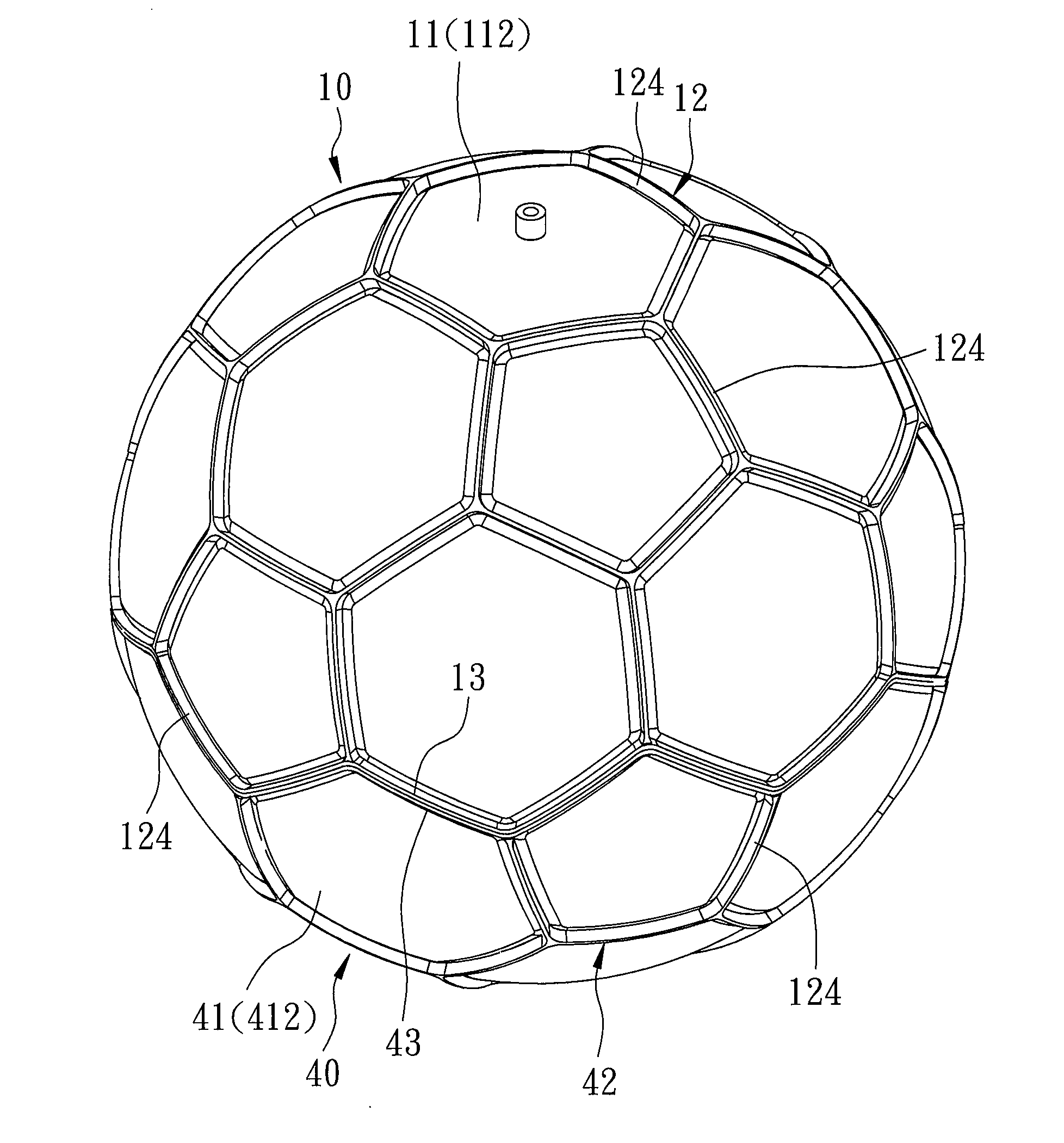
[0033]Referring to FIGS. 8 to 11, an inflatable ball according to the first preferred embodiment of this invention comprises a first half ball body 10, a second half ball body 40, and a valve unit 30.

[0034]The first half ball body 10 has a first half ball wall 11, a first rib structure 12, a first annular flange 13, and two first aligning elements 14, 15. The first half ball wall 11 has a first inner wall surface 111, a first outer wall surface 112, a through hole 113 extending through the first inner and outer wall surfaces 111, 112, and a first annular connecting edge 114 interconnecting circumferential ends of the first inner and outer wall surfaces 111, 112.

[0035]The first rib structure 12 is formed as one piece with the first half ball wall 11, and projects from one of the first inner and outer wall surfaces 11...


PUM


Abstract

An inflatable ball includes interconnected first and second half ball bodies. The first half ball body has a first half ball wall with first inner and outer wall surfaces, and a first rib structure formed as one piece with the first half ball wall and projecting from one of the first inner and outer wall surfaces. The first half ball wall has a through hole extending through the first inner and outer wall surfaces, and a first annular connecting edge interconnecting circumferential ends of the first inner and outer wall surfaces. The second half ball body has a second half ball wall with second inner and outer wall surfaces, and a second rib structure projecting from one of the second inner and outer wall surfaces. A valve unit is attached to the first half ball body in connection with the through hole.

Description

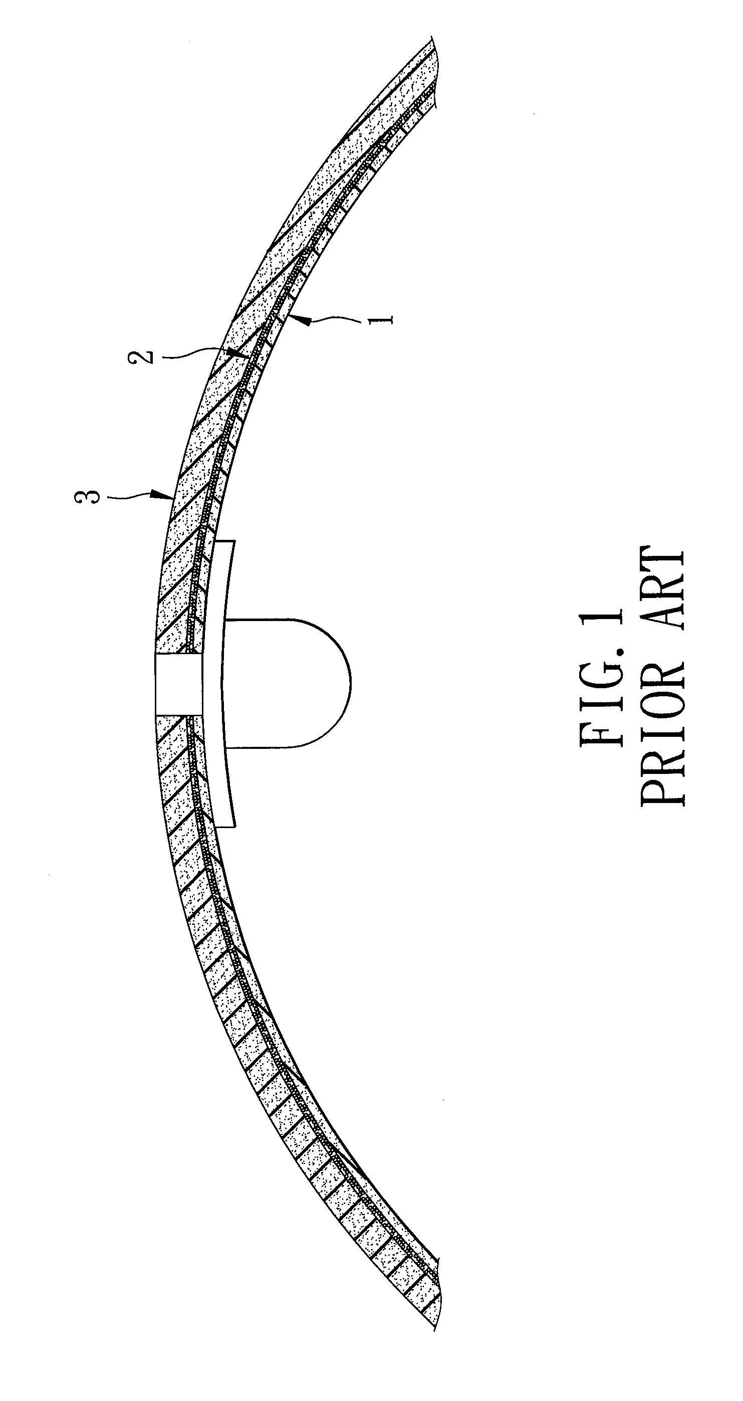
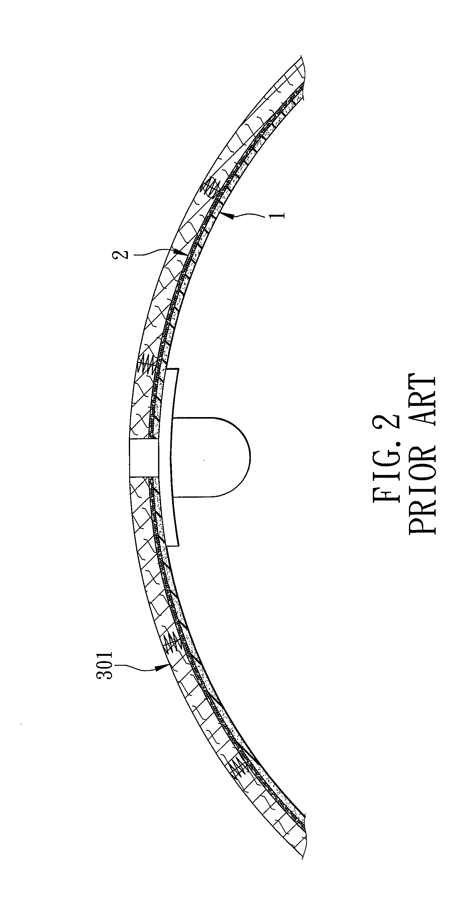
BACKGROUND OF THE INVENTION[0001]1. Field of the Invention[0002]This invention relates to a sports ball, and more particularly to an inflatable ball with a rib structure.[0003]2. Description of the Related Art[0004]A bladder of a conventional inflatable sports ball is made from either synthetic or natural rubber. To prevent swelling or deformation of the bladder due to increase of the inflation pressure, the following three manufacturing methods are usually employed:1. Wrapping Yarns Around the Rubber Bladder[0005]Referring to FIG. 1, a conventional inflatable ball includes a rubber bladder 1, a wrapping yarn layer 2 covering an outer surface of the rubber bladder 1, and a rubber outer cover layer 3 covering the wrapping yarn layer 2.[0006]Referring to FIG. 2, another conventional inflatable ball includes a rubber bladder 1, a wrapping yarn layer 2 covering an outer surface of the rubber bladder 1, and an outer cover layer 301 covering the wrapping yarn layer 2 and made from a plura...

Claims


Application Information

Patent Timeline
IPC IPC(8): A63B41/10A63B41/04
CPCA63B41/04A63B2041/005A63B41/10
Inventor LO, JACK
Owner LO JACK CORPORATION
Learn More