
Accommodating intraocular lens device

a technology of intraocular lens and lens capsule, which is applied in the field of accommodating intraocular lens devices, can solve the problems of shrinking the natural lens capsule about the device, affecting the effect of the device, and advancing cataracts to eventual vision loss and even complete blindness

Inactive Publication Date: 2013-02-28
LENSGEN INC
View PDF7 Cites 71 Cited by
  • Summary
  • Abstract
  • Description
  • Claims
  • Application Information

AI Technical Summary

Benefits of technology

The described intraocular lens (IOL) devices can change their shape and move forward and backward to mimic the natural eye's ability to accommodate. This allows the IOL devices to provide a broader range of accommodation that comes close to the natural eye.

Problems solved by technology

If left untreated, cataracts progress to eventual vision loss and even complete blindness.
One significant disadvantage to multifocal lenses is the possibility of visual distortions, particularly in the form of glare and halos around light sources at night.
Moreover, because the profile of the Crystalens® device is substantially smaller than that of the natural lens capsule, implantation of this device is followed by shrinkage of the natural lens capsule about the device.
As the natural lens capsule shrinks, the zonules are further stretched away from the ciliary muscles, with the attendant loss of the eye's accommodative range.
Dual-lens IOL devices generally suffer the disadvantage of being more complicated in design and requiring larger incisions in the eye for implantation.
While the dual-lens IOL devices may hold the potential for providing a greater range of accommodation, they represent a radical departure from the natural lens structure of the eye.
While accommodating IOL devices hold the promise of more fully restoring the natural range of vision for cataract patients, they still fail to substantially mimic the eye's natural mechanism of accommodation.
This is primarily because they rely solely on the eye's ciliary muscles to provide the accommodation and fail to respond to other forces which influence the natural accommodative process.

Method used


Image

  • Accommodating intraocular lens device
  • Accommodating intraocular lens device
  • Accommodating intraocular lens device

Examples


Embodiment Construction

[0037]Specific, non-limiting embodiments of the present invention will now be described with reference to the drawings. It should be understood that such embodiments are by way of example only and merely illustrative of but a small number of embodiments within the scope of the present invention. Various changes and modifications obvious to one skilled in the art to which the present invention pertains are deemed to be within the spirit, scope and contemplation of the present invention as further defined in the appended claims.

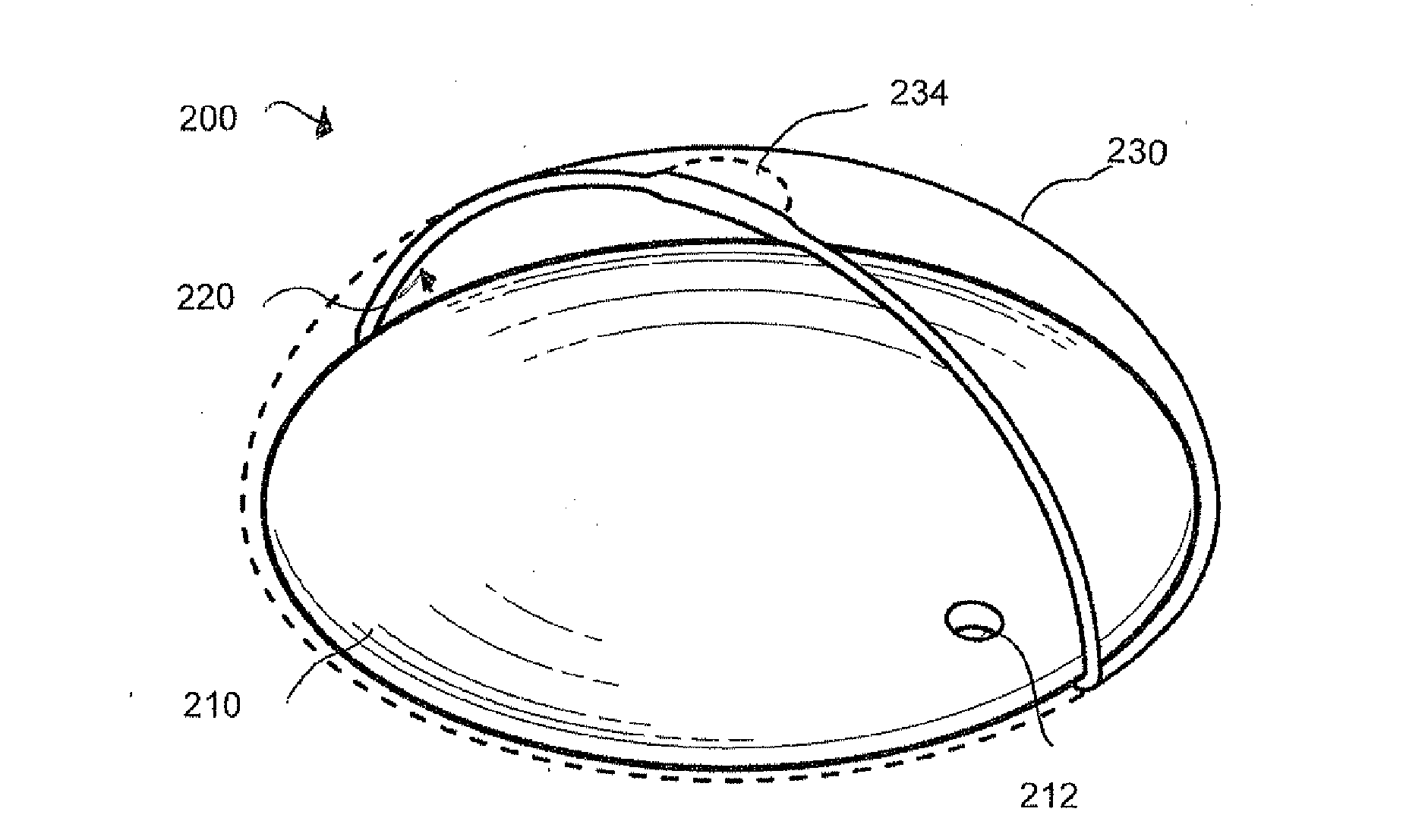
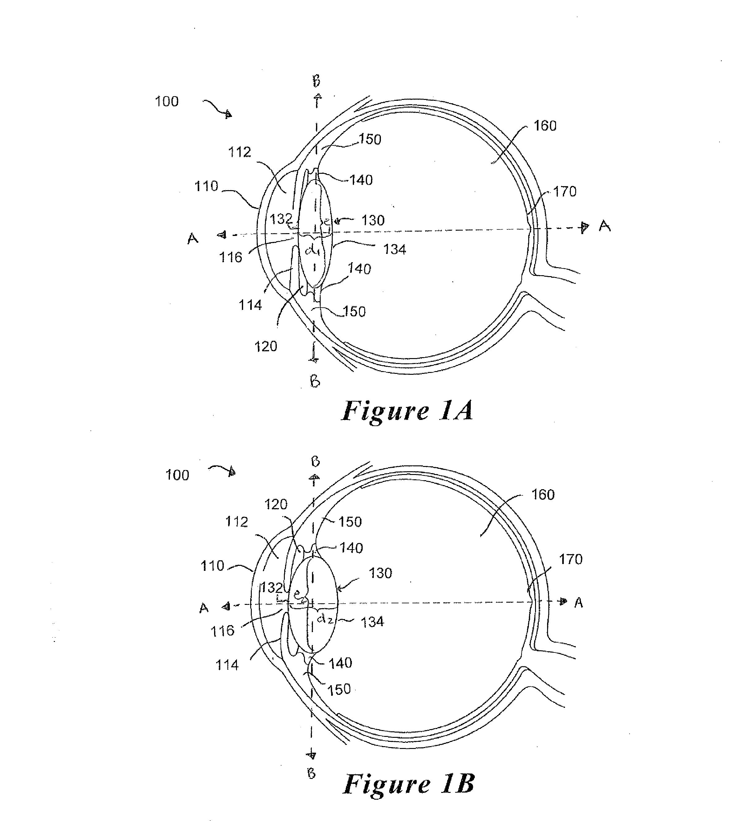
[0038]As shown in FIGS. 1A-B, the human eye 100 comprises three chambers of fluid: the anterior chamber 112, the posterior chamber 120 and the vitreous chamber 160. The anterior chamber 112 corresponds generally to the space between the cornea 110 and the iris 114 and the posterior chamber 120 corresponds generally to the space bounded by the iris 114, the lens 130 and zonule fibers 140 connected to the periphery of the lens 130. The anterior chamber 112 and th...


PUM


Abstract

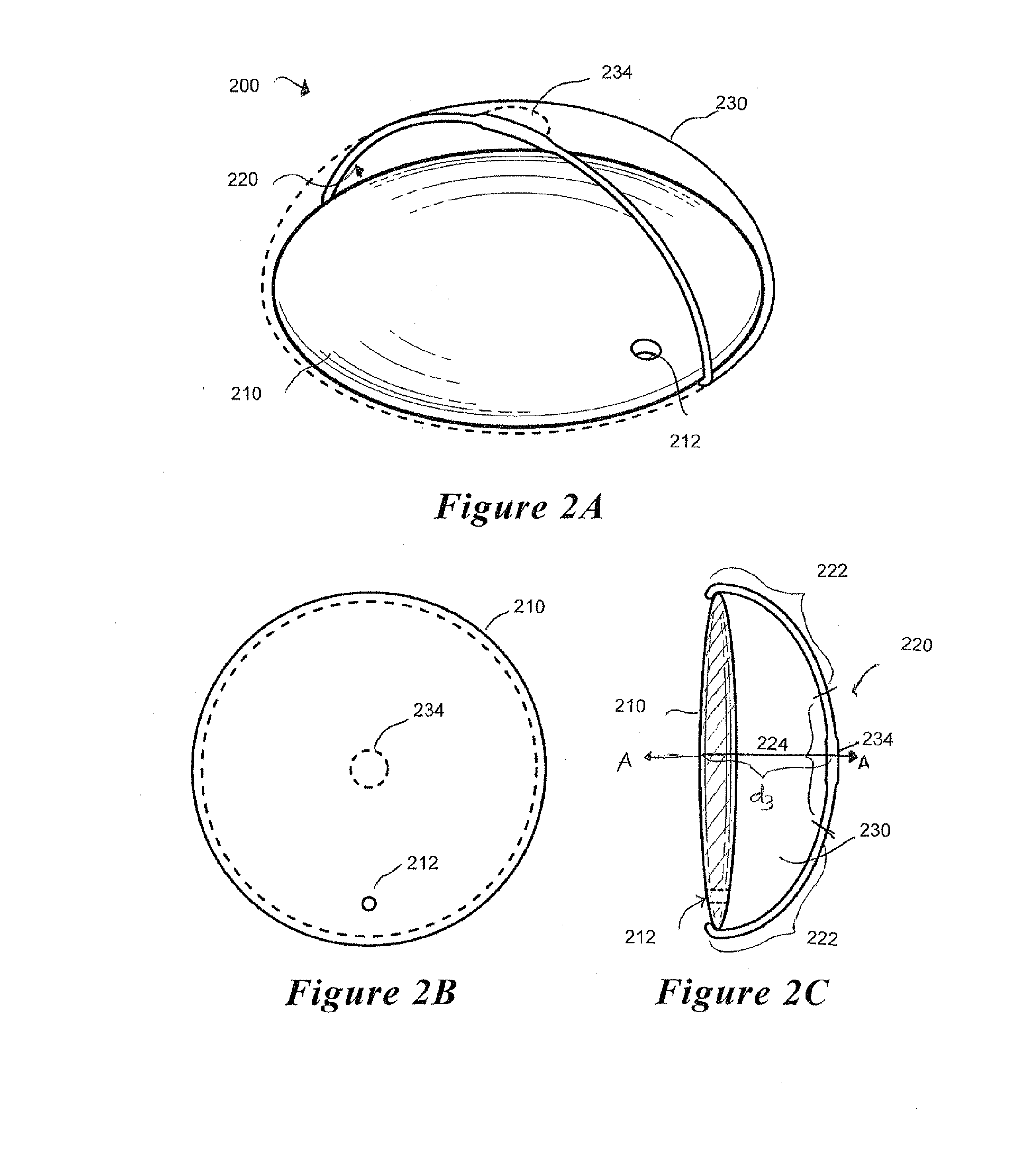
An accommodating intraocular lens (IOL) device adapted for implantation in the lens capsule of a subject's eye. The IOL device includes an anterior refractive optical element and a membrane coupled to the refractive optical element. The anterior refractive optical element and the membrane define an enclosed cavity configured to contain a fluid. At least a portion of the membrane is configured to contact a posterior area of the lens capsule adjoining the vitreous body of the subject's eye. The fluid contained in the enclosed cavity exerts a deforming or displacing force on the anterior refractive optical element in response to an anterior force exerted on the membrane by the vitreous body. The IOL device may further include a haptic system to position the anterior refractive optical element and also to engage the zonules and ciliary muscles to provide additional means for accommodation.

Description

FIELD OF THE INVENTION[0001]The invention relates generally to an accommodating intraocular lens device and, more particularly, to an accommodating intraocular lens device configured for implantation in a lens capsule of a subject's eye.BACKGROUND[0002]A cataract is a clouding of the lens in the eye that affects vision. While most cataracts are related to aging, cataracts may also develop as a result of traumatic eye injury, glaucoma, diabetes, steroid use, and exposure to radiation, to name a few. If left untreated, cataracts progress to eventual vision loss and even complete blindness.[0003]Cataracts are typically treated by surgically removing the clouded lens matrix and implanting a replacement artificial intraocular lens (IOL) in the lens capsule that remains. The first generation of implanted IOL devices comprised monofocal lenses, which provided vision correction at only a single distance. Thus, while monofocal lenses provided distance vision, corrective lenses were still req...

Claims


Application Information

Patent Timeline
Patent Type & Authority Applications(United States)
IPC IPC(8): A61F2/16
CPCA61F2/1635A61F2250/0018A61F2002/1682A61F2002/16901
Inventor RAO, RAMGOPALMILLER, DAVID
Owner LENSGEN INC
Learn More