Downhole torque limiter and method

a torque limiter and torque limiter technology, applied in the field of drill strings, can solve problems such as limiting torque transmission, and achieve the effect of limiting torque transmission

Inactive Publication Date: 2013-03-07
NICHOLS MARK B
View PDF12 Cites 7 Cited by
  • Summary
  • Abstract
  • Description
  • Claims
  • Application Information

AI Technical Summary

Benefits of technology

[0010]The present invention provides an axial load and pressure compensated torque limiting device that may be positioned between upper and lower portions of a drill string. When torque between the two portions exceeds a predetermined limit, relative rotation is permitted, thus limiting torque transmission. Relative rotation between the upper and lower sections is preferably resisted by frictional forces between various plates that are compressed together and, thus, preset by axial pressure. Such plates are preferably rotatably restrained to the upper and lower extremities of the device in an alternating pattern via external and internal interfaces. A compensation system is provided to compensate for varying axial pressure, such that external compressive and tensile loads do not alter the axial pressure applied to the plates and, thus, the friction between them. In a preferred embodiment, such a compensation system comprises preloaded spring assemblies which tend to maintain constant pressure between contacting plates. A bore connecting the upper and lower extremities is provided, thus, permitting free passage of fluids.

Problems solved by technology

When torque between the two portions exceeds a predetermined limit, relative rotation is permitted, thus limiting torque transmission.

Method used


Image

  • Downhole torque limiter and method
  • Downhole torque limiter and method
  • Downhole torque limiter and method

Examples


Embodiment Construction

1. General Features

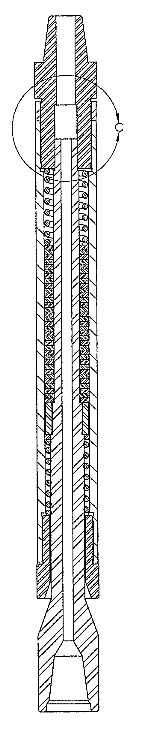
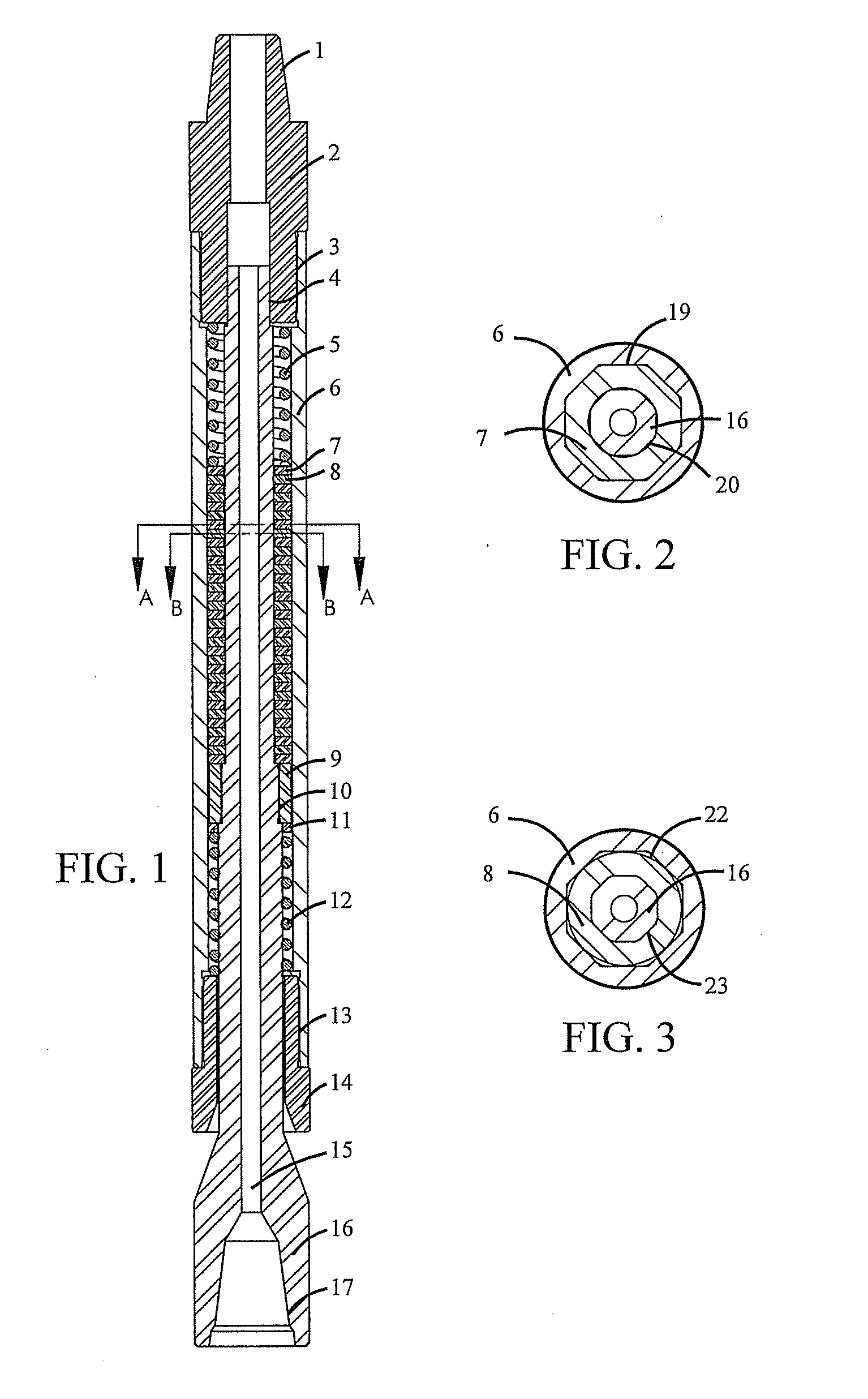
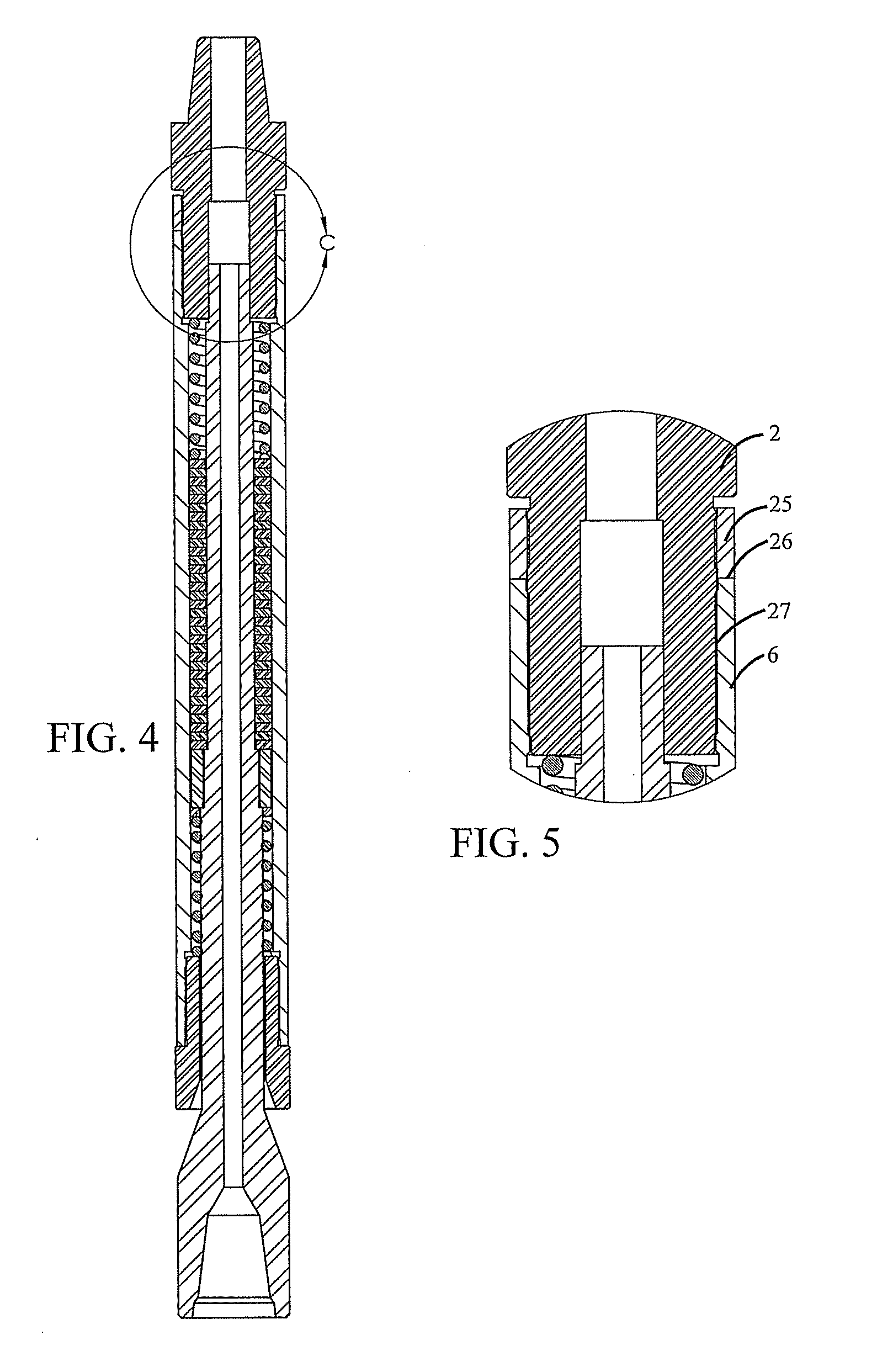
[0042]Referring to FIGS. 1-15, there is shown a downhole torque limiter 38 in accordance with various embodiments. As used herein, the terms “a” or “an” shall mean one or more than one. The term “plurality” shall mean two or more than two. The term “another” is defined as a second or more. The terms “including” and / or “having” are open ended (e.g., comprising). The term “or” as used herein is to be interpreted as inclusive or meaning any one or any combination. Therefore, “A, B or C” means “any of the following: A; B; C; A and B; A and C; B and C; A, B and C”. An exception to this definition will occur only when a combination of elements, functions, steps or acts are in some way inherently mutually exclusive.

[0043]Reference throughout this document to “one embodiment,”“certain embodiments,”“an embodiment,” or similar term means that a particular feature, structure, or characteristic described in connection with the embodiment is included in at least one embodiment...


PUM


Abstract

The downhole torque limiter and method eliminate damage to downhole components by eliminating excessive torque transmission. The device comprises a housing, compression assemblies, and anti-rotation plates. Inner and outer assemblies of the device are permitted to slip with respect to each other after reaching a settable torque limit which is preferably below the maximum capacity of other downhole components. The device may be positioned in drill strings that comprise a downhole motor and/or drill bit as well as drill strings that do not comprise a downhole motor and/or drill bit. In drill strings comprising a downhole motor and/or drill bit, the device may be positioned below the downhole motor and above the drill bit, adjacent to and above the downhole motor, or above the downhole motor such that at least one drill string joint is positioned between the device and the downhole motor.

Description

[0001]This application claims benefit from U.S. Provisional Patent Application No. 61 / 529,975, filed Sep. 1, 2011.BACKGROUND OF THE INVENTION[0002]1. Field of the Invention[0003]This invention generally relates to drill strings and related equipment as typically used in the oil and gas industry. More specifically, this invention relates to a device and method that limit torque transmission such that equipment is protected from overload and damage.[0004]2. Description of the Prior Art[0005]Drilling and well service operations may be performed with a rotating or non-rotating drill string composed primarily of tubular members and which may also contain a fluid driven downhole motor. Torque is delivered from the surface to the bit, mill, or other device via transmission through the drill string. If utilized, a downhole motor provides additional torque and rotation near the bit, mill, or other device by converting hydraulic energy from the drilling fluid into mechanical power.[0006]Drill...

Claims


Application Information

Patent Timeline
Patent Type & Authority Applications(United States)
IPC IPC(8): E21B17/03
CPCE21B4/02E21B44/04
Inventor NICHOLS, MARK B.
Owner NICHOLS MARK B
Why Eureka
Try Eureka