Shock absorbing device for watercraft propeller

a technology of shock absorption device and propeller, which is applied in the direction of marine propulsion, rotors, vessel construction, etc., can solve the problems of inability to transmit the torque necessary to rotate the propeller at high speeds, the configuration of the propeller can be problematic at high speeds, and the rubber damper is not able to dampen the shock. to achieve the effect of limiting the torque transmitted

Inactive Publication Date: 2007-03-08
YAMAHA MOTOR CO LTD
View PDF16 Cites 11 Cited by
  • Summary
  • Abstract
  • Description
  • Claims
  • Application Information

AI Technical Summary

Benefits of technology

[0015] In accordance with another embodiment, a shock absorbing device for a watercraft propeller can comprise an outer tube unitarily formed with a blade of a propeller, an inner tube positioned in the outer tube and coupled with a propeller shaft, and an intermediate tube positioned between the outer tube and the inner tube. The device can also include a first dampening device placed between the intermediate tube and the outer tube and a second dampening device placed between the intermediate tube and the inner tube. One of the first and second dampening devices is fixed in place so as to absorb shocks and the other of the first and second dampening devices is fit into place so as to limit torque transmitted thereby.

Problems solved by technology

Nevertheless, the JP '983 rubber damper has such a small spring constant that it is unable to transmit the necessary torque to rotate the propeller at high speeds.
However, this rubber damper is not able to dampen the shock made when the dog clutch of the shift mechanism is engaged.
Such a configuration can be problematic at high speeds.
If the propeller strikes an object while rotating at a high speed with the metal portions of the engaging nested, some members of the power transmission system can be damaged.
In particular, the propeller and other members that have relatively low rigidity are likely to be damaged.
Employing such a structure is complicated however, and would require that the outboard motor have a first rubber damper disposed inside of a housing thereof and a second rubber damper disposed inside of the propeller.

Method used


Image

  • Shock absorbing device for watercraft propeller
  • Shock absorbing device for watercraft propeller
  • Shock absorbing device for watercraft propeller

Examples


Embodiment Construction

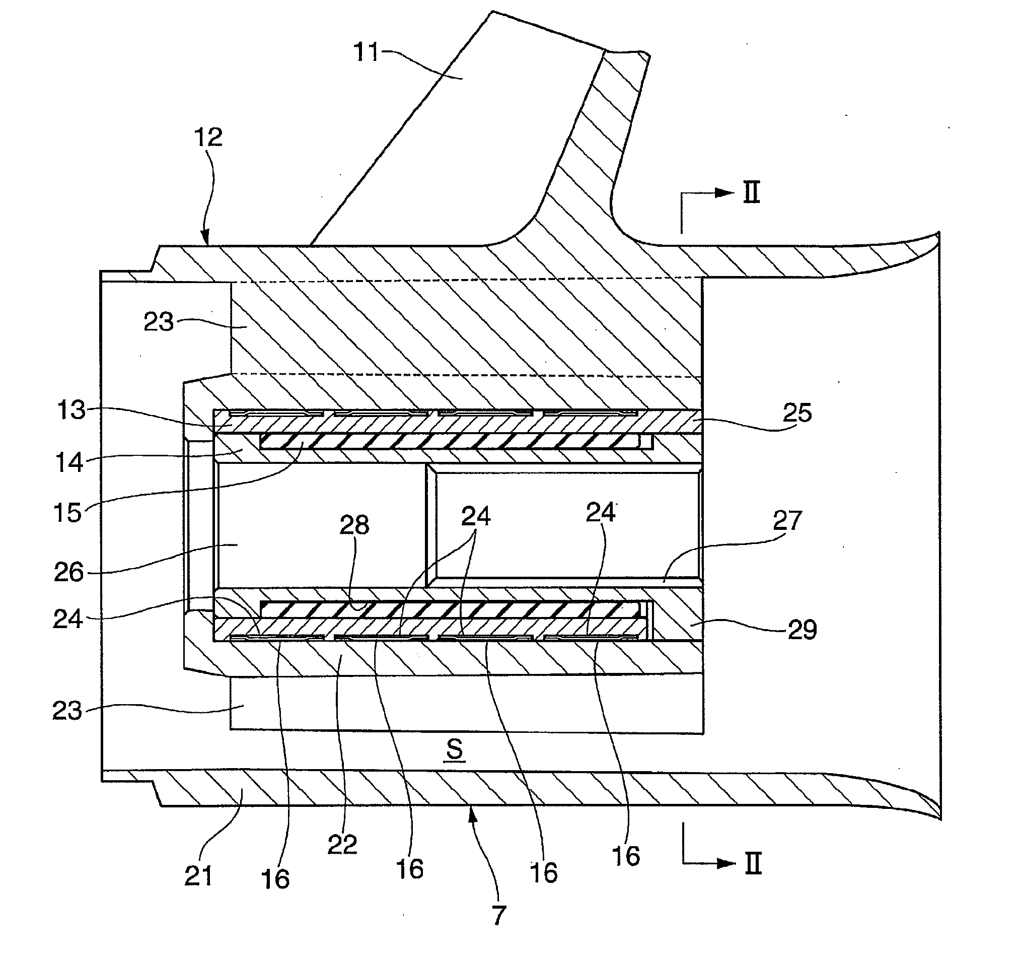
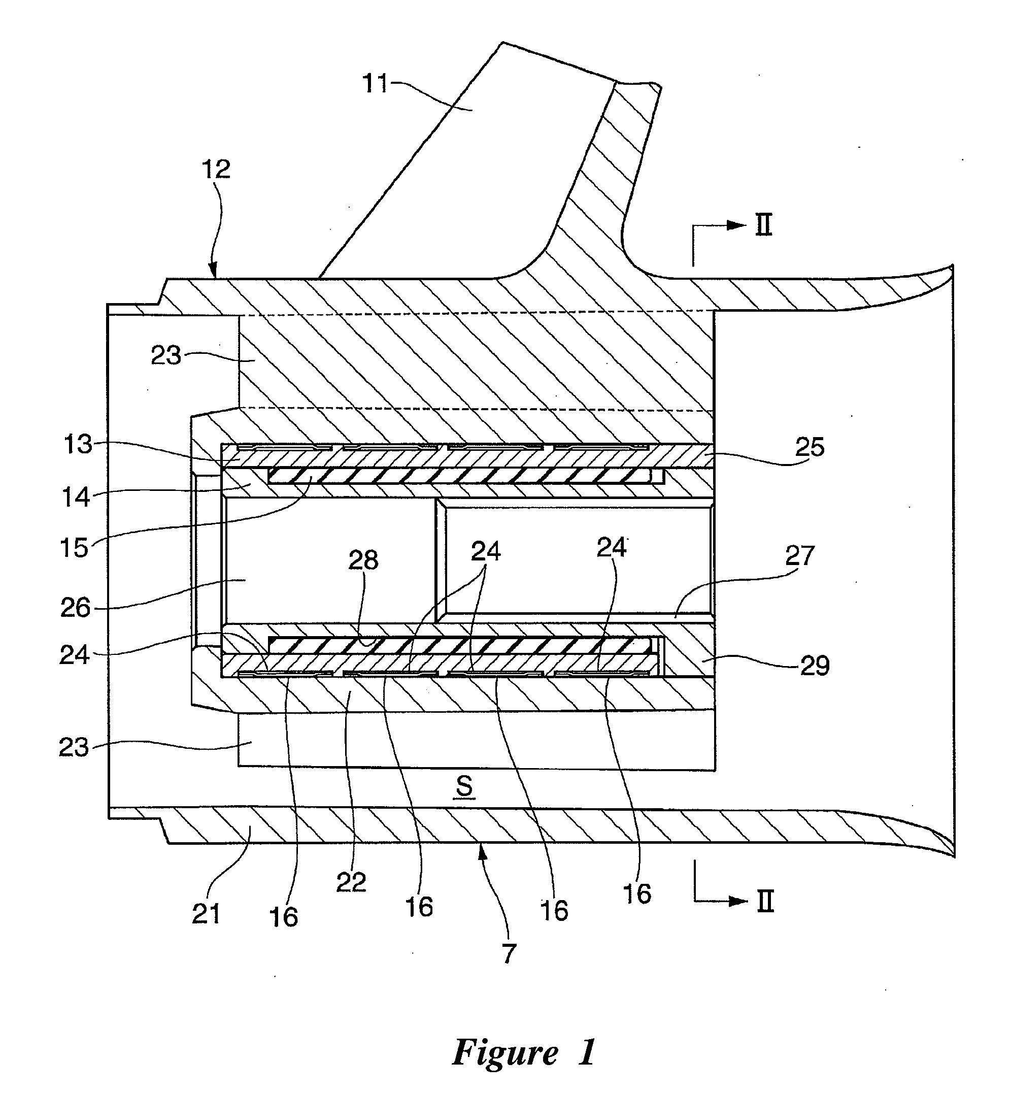
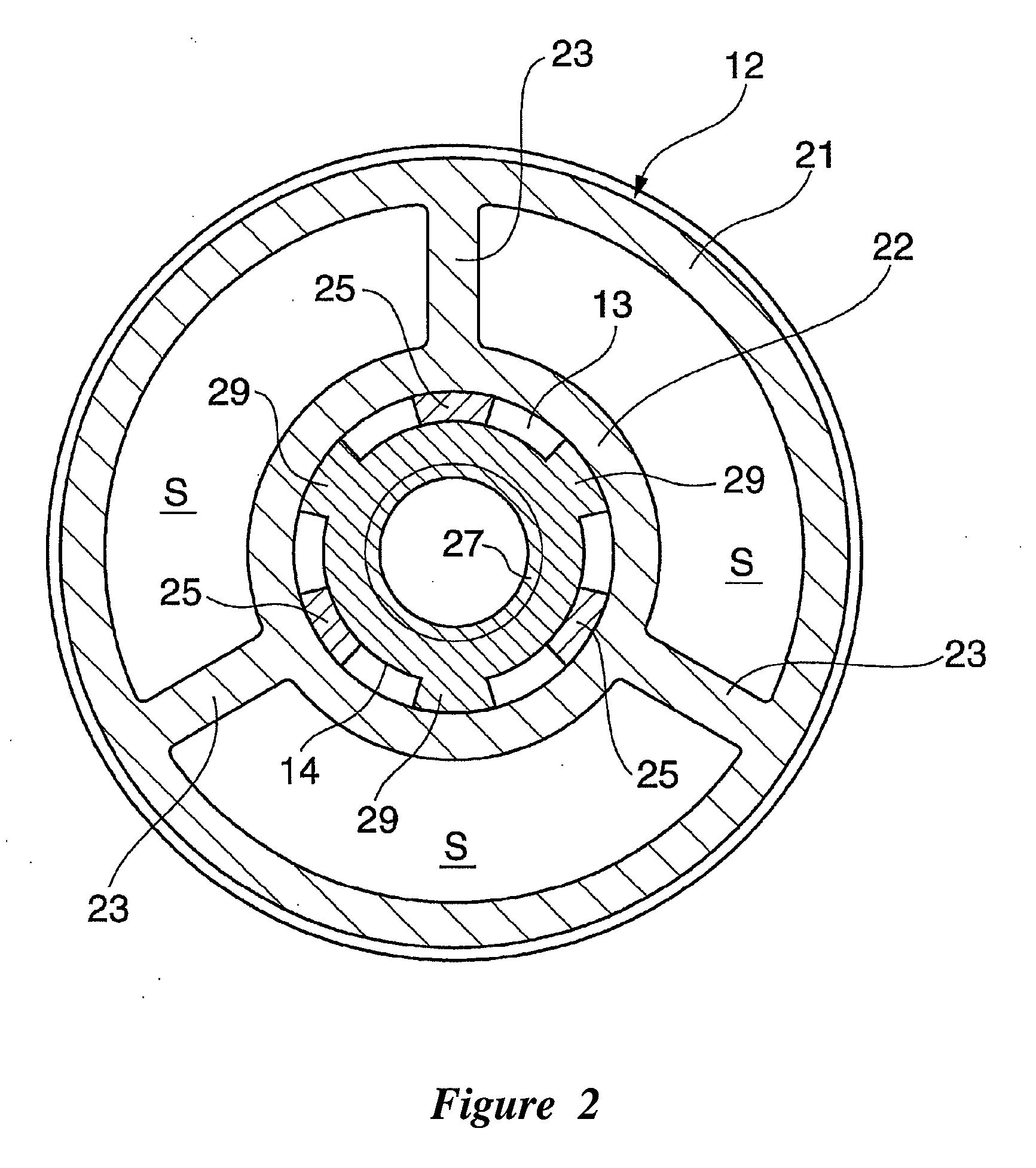
[0023] With reference to FIGS. 1 through 6, an embodiment of a shock absorbing device for a watercraft propeller 7 formed in accordance with the present invention will be described below. The propeller merely exemplifies one type of environment in which the present inventions can be used. However, the various embodiments of the shock absorbing devices disclosed herein can be used with other types of devices that benefit from shock absorption, for example, but without limitation, rotational shaft connections designed to absorb and thus prevent the transfer of shock energy from one shaft to another. Such applications will be apparent to those of ordinary skill in the art in view of the description herein. The present inventions are not limited to the embodiments described, which include the preferred embodiments, and the terminology used herein is not intended to limit the scope of the present inventions.

[0024]FIG. 1 is a vertical cross sectional view of a propeller incorporating a s...


PUM


Abstract

A shock absorbing device for a watercraft propeller is provided that can include an outer tube unitarily formed with blades of a propeller. An inner tube can be coupled with a propeller shaft. An intermediate tube can be positioned between the outer tube and the inner tube. A first damping means can be placed between the intermediate tube and the outer tube. A second damping means can be placed between the intermediate tube and the inner tube. One of the damping means can include a rubber damper interposed between the inner tube and the intermediate tube, and an engaging means for limiting an angle range in which the inner tube and the intermediate tube can be rotatable relative to each other to a predetermined angle range. The rubber damper can have a spring constant with which elastic deformation thereof begins at a moment that the propeller shaft initiates its rotation. The other damping means includes a torque limiter (tolerance rings 16) having a circumferential surface that slips against frictional resistance.

Description

CROSS-REFERENCE TO RELATED APPLICATIONS [0001] The present application is based on and claims priority under 35 U.S.C. § 119 to Japanese Patent Application No. 2005-258934, filed on Sep. 7, 2005, the entire contents of which is expressly incorporated by reference herein. BACKGROUND OF THE INVENTIONS [0002] 1. Field of the Inventions [0003] The present invention relates generally to watercraft propulsion, and more specifically, to a watercraft propeller having a damper interposed between a propeller shaft and a blade of a propeller. [0004] 2. Description of the Related Art [0005] A common watercraft propulsion device, such as an outboard motor, typically includes a propeller to produce thrust for propelling the watercraft. Some propellers incorporate a rubber damper interposed between a propeller shaft and blades. Such a propeller is disclosed, for example, in Japanese Patent Document No. JP-A-Sho 59-171789 (see pages 4 and 5, FIG. 1) (hereinafter “JP '789”). JP '789 discloses that t...

Claims


Application Information

Patent Timeline
Patent Type & Authority Applications(United States)
IPC IPC(8): B63H21/30B64C11/24B63H1/15F01D5/18F03B3/12F03D11/02F04D29/38
CPCF04D13/02B63H23/34
Inventor HARADA, HIROSHI
Owner YAMAHA MOTOR CO LTD
Why Eureka
Try Eureka